Bristol #0 with mods

Kelly McLaughlin

Well-Known Member
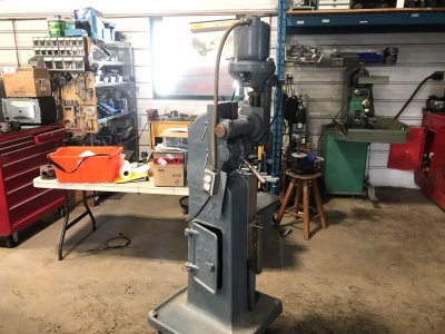
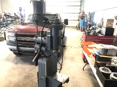
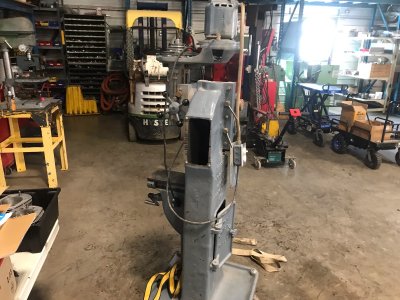
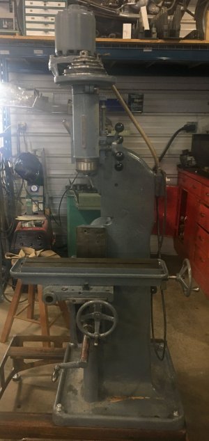
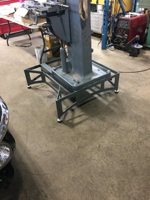
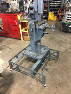
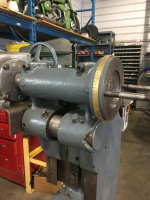
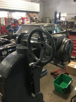
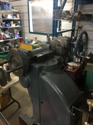
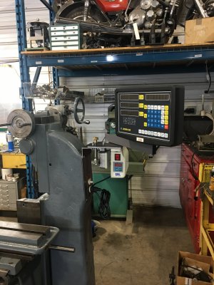
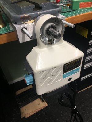
Hi Folks! Bought this several years ago and it's finally it's turn in the shop. Started life as a Horizontal knee mill but has been heavily modified over time and is now a vertical knee mill with a rack that moves the head assy about 4 inches. It has a knee , x and y like normal from research the x was originally a rack it looks like some kind of additional rack like the z on a mini mill, then a 4" quill. All in all should be a nice versatile little machine and a fun project. The head appears to be a 1/3 Hp Halco 5 spd, the quill is fine feed only, the spindle is B&S #7 but with as sturdy as the machine is and I think I'll put a 1HP DC servo on it, which would make it a candidate for R8 so the rest of my tooling will fit it. We'll see how complicated that gets. It's short so I have to make a base / riser for it, the original base is tiny and with the vertical head it's top heavy. first I'll assemble it and debug it then start figuring out how to proceed. definitely a dro and an x axis power feed and it's homely so we'll clean it up and make it purdy : ) I'll post pics as things progress.
 

Attachments

  • 699056702.JPG
    699056702.JPG
    314.4 KB · Views: 72
  • 699056725.JPG
    699056725.JPG
    333.5 KB · Views: 72
  • 699056687.JPG
    699056687.JPG
    467 KB · Views: 71

Kelly McLaughlin

Well-Known Member
I've been corresponding with a fellow on Practical machinist that has an unmolested version of this mill. this one has a lead screw on the x axis but his original has a rack like the one that lifts the head on the table he said he's not used it for that reason the table travel is too quick to be very useful. Anyone have any ideas what the intended use may have been? It seems like something that may have bee built for a particular job or industry. I'm down with a cold bit itching to get at this one. How are things Rudy? I'm going to put the SM to work making parts for this one!
 

Kelly McLaughlin

Well-Known Member
Hi John! Actually that isn'y mu shop, I have a small corner that when I retired and closed my shop a friend gracefully offered the space. as you see I took him up on it. I do my best to keep my creep to a minimum but there's so many interesting things to play with : ) now that I have some time!
 

Rauce

Ultra Member
Anyone have any ideas what the intended use may have been? It seems like something that may have bee built for a particular job or industry.

I used to have a similar horizontal mill with a rack feed on the head and a rack feed on the table X.

It was a Williams M-51, made in Brantford. Best I could tell it was built during WW2 and likely used in a munitions factory.
 

Kelly McLaughlin

Well-Known Member
I was looking through a book I have on tool making and lo and behold there's a mill similar to what mine started life as. they call it a "hand mill" I attached the pic and small write up
 

Attachments

  • IMG_0455-1.JPG
    IMG_0455-1.JPG
    445.9 KB · Views: 5
  • IMG_0456-1.JPG
    IMG_0456-1.JPG
    445 KB · Views: 5

Kelly McLaughlin

Well-Known Member
Got the Mill mostly assembled, made a stand so I don't have to stoop to use it. got the Y pretty well dialed in. The X will be a bit of a challenge it seems when the conversion was done they were short on material so the x lead screw only goes a little more than 1/2 way under the table so I've got some material coming to make a new lead screw and nut.
Specs on this little mill appear to be:
X travel currently 12 inches should be 18 ish once the new parts are made.
y travel is 3.75 inches
Z total space is 14.5 Knee travel is just over 12 inches
Quill is 4 inches and fine feed only
The rack that moves the headstock up and down is 4 inches, it's the same type of thing that was originally on the table instead of the lead screw.
Next will be to start figuring out If I can realistically make the spindle an R8 the B&S 7 is just too small to be usefull and I had a quick peek at the spindle bearings late today and they are definetly big enough to handle the R8.
 

Attachments

  • IMG_0463.JPG
    IMG_0463.JPG
    249.1 KB · Views: 7

Kelly McLaughlin

Well-Known Member
Got looking closely at the table on this mill and realized whoever removed the x axis rack and added the lead screw Had the table on backwards : ) So it's now in the tiny shop getting the other end machined for an end block which will allow me to add a thrust bearing at the New Hand wheel / power feed end. Once my lead screw stock gets here a bushing at the other end for support. I found an R8 spindle that will cut down to this mills dimensions and a set of precision spindle bearings that will allow the bigger spindle in the quill bore with no mods to the headstock. Making Progress. : ). If anyone has need for a 3/4-8 acme tap in future I will have one : ).
 

Kelly McLaughlin

Well-Known Member
Got my R8 spindle and new bearings this week, Good thing the donor spindle wasn't any longer The tailstock was almost off the bed : ). Almost finished the mods to fit it to the spindle housing. Should have some pics of the drive and rotation mechanism for the head this week. lots of fabrication on this project : )
 

Attachments

  • IMG_0503.JPG
    IMG_0503.JPG
    399 KB · Views: 5
  • IMG_0504.JPG
    IMG_0504.JPG
    387.5 KB · Views: 5

Kelly McLaughlin

Well-Known Member
Getting things mocked up, making slow progress. The gear reducer on the head rotation is very smooth, using the x axis hand wheel for testing I have a nice compact wheel to install. With the reduction in weight by adding the servo motor it shouldn't fall at the 45 degree point.... I hope : ) should know next week.
 

Attachments

  • IMG_0505.JPG
    IMG_0505.JPG
    407.3 KB · Views: 8
  • IMG_0506.JPG
    IMG_0506.JPG
    367 KB · Views: 8
  • IMG_0507.JPG
    IMG_0507.JPG
    399.2 KB · Views: 8
  • IMG_0508.JPG
    IMG_0508.JPG
    366.7 KB · Views: 9
  • IMG_0509.JPG
    IMG_0509.JPG
    471.3 KB · Views: 8
Top