• Scam Alert. Members are reminded to NOT send money to buy anything. Don't buy things remote and have it shipped - go get it yourself, pay in person, and take your equipment with you. Scammers have burned people on this forum. Urgency, secrecy, excuses, selling for friend, newish members, FUD, are RED FLAGS. A video conference call is not adequate assurance. Face to face interactions are required. Please report suspicions to the forum admins. Stay Safe - anyone can get scammed.
  • The 2026 Calgary Area Meetup is set for Saturday May 30th at 10am. The signup thread is here! Robinhood has graciously offered to host the meetup again this year. Please note that you MUST RSVP to the notice linked above if you wish to come.

Automotive electrical repair question

Update:

Got the relay from a local auto parts dealer who had to bring it in from Calgary. Ordered Tuesday morning and picked it up Wednesday afternoon. Has 5 terminals but I will only be needing 4. Less than $13.00. If ordered from online electrical parts website, including shippping, over $23.00. One inch cube not including length of terminals.
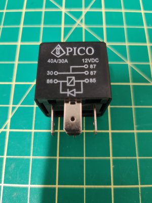
Relay.jpg
 
Really getting into the tall weeds here but I know there are far more experienced electronics people here that likely can shed some light.

(1) From a couple different sources I am getting this feedback that connecting my relay in parallel with the existing might be better engineering incase disconnecting the connection at terminal 2D causes upstream problems (feeds something in the BCM that is unknown). I am leaning towards that isn't a likely issue. Here is another item that seems to support NOT going that route. I may or may not have interpretted this correctly from information regarding another automotive relay I was considering before selecting the PICO brand:

"Any diode or pn-junction parallel to the coil (internal or external) will significantly decrease the electrical lifetime, especially when used for inductive loads."

So 2 unknown diodes operating in parallel with 2 relay coils, each diode designed to work with the coil it is paired with but sharing a circuit with another paired set - possible conflict? If one diode in parallel shortens the coil's lifespan what will a second do? Maybe not much but that's not what the original design intended - right?

(2) It was suggested "why tap all three outputs when tapping one will feed all 3"? Well, it would require using one wire of a certain ampacity to backfeed into the BCM to a PCB trace (I assume) of a higher ampacity (maybe) back to output wires of a smaller ampacity (fairly confident). Even if I chose the largest ampacity wire of the 3 (maybe the taillights wire) it was likely not sized to handle continuous current for all 3 outputs. I am likely being overly cautious because I know these runs will be very short and that helps with handling a higher load but I think I will play it safe and stick with as close to the original design as possible, no short-cuts.
 
The FWD will slightly slow down the release time of the relay contact, that’s what the note is about. So especially with inductive loads that slower release extends the arc time at the contact when it opens. We’re talking about perhaps a few ms at most.

That being said, you don’t have a choice, leave the diode out and the coil voltage will spike to about 100+ Volts when the relay is de-energized, and that will pooch the driver either quickly or before long. One or two diodes in parallel won’t change the timing.
 
I agree with Slow Poke.

Yes, the diode decreases the service life of the relay by increasing the time that it takes for the contacts to close or open which increases the contact damage rate.

But you really have no choice. It's a matter of accepting the reduced contact life associated with a slower relay or destroy the drivers more or less instantly.

For most relay applications, less contact life means virtually nothing. Instead of 1,000,000 cycles, you get 500,000. So what?

The relay comes with a diode for a reason. With normal loads, the contacts will perform as expected with the diode.

Where things get fuzzy is when you have loads that are hard on contacts. High current, inductive, etc. Both are hard on contacts.

Once you have a working circuit, go get a few extra relays and forget about it.
 
While we are in “relay school”….

Take a typical small relay rated for 250V ac/dc

The rating at 250Vac might be 10-15A,
The rating for 250Vdc would only be say 1A.

Why, because with ac, every 8.3ms the voltage goes to zero as the sinewave crosses through the zero point. With a resistive load, 0V, = 0 current. So no arc to break.

DC, the contact has to break the arc.

AC with inductive load, similar to dc, but not quite as bad.

Common trick when switching inductive loads is to time the de-energization for near the zero cross taking into consideration the relay drop out time and L-R characteristic. Might help a little for a few lines of code. Or use an arc snubber.

Hats off to you Elektrisun for your curiosity.
 
Most of those 1" cube relays use a resistor across the coil terminals not a diode. If they used a diode the polarity would need to be correct or the diode would be damaged.
 
Update - main connections made other than the lighting circuit. I will test the relay operation and voltage output before connnecting to the BCM light outputs. Plan is to only connect one circuit first and see if the lights work. One connection should pwoer all. I already checked that the BCM light circuit outputs - 1X, 80, and 4D - are all common to each other.
 
When troubleshooting (properly designed) electronics, if there is something mechanical in the circuit I suspect it before the electronics. Connnectors, switches and RELAYS are often the weak link. Next up anything that runs over 50 deg C. ( when ambient is 20 deg C.)

Good job on the repair!
 
Last edited:
When troubleshooting (properly designed) electronics, if there is something mechanical in the circuit I suspect it before the electronics. Connnectors switches and RELAYS are often the weak link. Next up anything that runs over 50 deg C. When ambient is 20 deg C.

^ This

Except I always put electrical connections in a category of their very own at the very top of the list.

A true story. Back in the early 80s I worked as a trouble shooter in the advanced diagnostics group at our automotive corporation. Basically, we got the cars that the dealers and regional service people couldn't fix. I don't think I ever saw a car or truck that hadn't had all the electronic control boxes replaced needlessly - sometimes several times! Usually the investigation showed that they were the first things changed.

Fundamentally, the dealer service people were replacing what they didn't understand. (I don't know whats in that black box so it must be the problem). That belief needlessly drove the warranty numbers sky high for the electronics.

It's been 40 years since I was directly involved but human nature doesn't change easily. I bet that's still true today.

Bottom line. Check the connections first, then the switches and RELAYS, then all the stuff that moves. Leave the black boxes to last.
 
Hi Susquatch, Guys,
Changing a black box stems from the old TV/Radio days, it was always a valve(Tube) that failed never a resistor that changed value because it was over loaded and got hot ! Or a capacitor that went open circuit !
 
I still have the old magazine that told Dad how to fix the RCA from the 60’s I think we were 9 or 10 riding our bikes to the drugstore to test the tube. The thing I remember most is him grounding the picture tube and the brilliant flash of electricity.
 
Back
Top