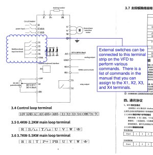
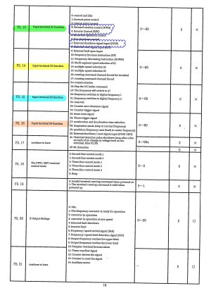
the 3-phase output from the VFD measures about 485 - 500 volts when set for 60 Hz speed.
I recently had to do a massive amount of research to design a Solar PV system for my friend's home. Not some little 6kw system, not even some 10 or 12kw system to be able to use fast track approval, but a substantial 26kw system to meet his special rural home and shop needs. I already knew that there are many parallels between a solar inverter and the inverters in VFDs but I managed to answer many questions that I had no previous answers for.
Since China is the global leader in solar equipment, and serves the globe I had to compare Canada's grid to those of EU and China to be able to distinguish what inverters worked on what grids, and how and why they were different, and the relevant standards that equipment must meet to be connected to Canadian power grids.
I certainly undersatnd various solar inverter issues now, and have cracked the code to be able to buy direct from chinese PV solar equipment distributors and save a bundle of cash. It also helped me finally understand "boost" model of VFD which I'd seen many times in the past and just said "huh."
OH and I understand why a solar PV inverter can have downstream transformers, when a chinese VFD will fry a downstream transformer.
A VFD creates an AC waveform for a raw motor that is completely isolated from the utility grid. Because it dictates the electrical environment entirely by itself, a VFD can dump raw, jagged pulse width modulation voltage pulses right down the wire to the motor. If you feed those square waves into your step up transformer and/or into the machine's internal control transformer, those high frequency pulses will cause severe harmonic distortion. The control transformers will hum intensely, overheat, and fail.
Because of the same dangers, a grid tied solar inverter MUST DO the exact opposite, it must perfectly match and merge with the existing utility grid. High frequency output passes through an internal, highly sophisticated multistage LC (Inductor-Capacitor) filter network. This filtering network catches the rapid IGBT square wave pulses and smooths them out completely, delivering a pure sine wave with less than 3% total harmonic distortion.
In Ontario, to legally tie into Hydro One or your local utility, an inverter must be certified to UL 1741 / CSA C22.2 No. 107.1 standards to prove capable of delivering the less than 3% total harmonic distortion. These strict utility standards dictate that the inverter cant dump raw high frequency PWM switching noise into the electrical panel, or it would corrupt the grid's power quality and violate anti islanding/safety rules.
Anyway, back to the fellows VFD.
To truly understand why these "boost" VFDs exist, we have to look at the Chinese power grid. These drives were engineered strictly for China's domestic agricultural and rural cottage industries.
The Chinese industrial grid operates on a 380V wye system. But just like in Canada, utilities will not drop a true, commercial 3ph line to a residential garage, an alleyway workshop, or a rural family farm due to the massive infrastructure and connection costs.
Instead, what those residential & rural customers get is a single phase connection. But unlike Canada’s 120V/240V split phase system, which uses a center tapped transformer to give you two hot legs, China distributes power as a true single 220V Hot line and a Neutral line. Basically every last piece of industrial equipment in China has a 3ph 380volt motor.
This created a massive problem for millions of small Chinese operators. Every affordable, mass produced tool available on their domestic market, from irrigation water pumps and crop hullers to small machine shop lathes, comes natively equipped with a 380V 3ph induction motor, because 3ph motors are vastly cheaper, simpler, and tougher to manufacture than single-phase motors.
Faced with a 220V single phase wall outlet and a 380V 3ph piece of machinery, Chinese electronics manufacturers designed a decentralized workaround. They realized they could skip expensive copper transformers entirely. They stuck voltage doubling rectifier circuit, aka a silicon charge pump, on the front end of a cheap VFD.
By rapidly dumping the incoming 220V AC peaks back and forth into capacitors connected in series, they can double the internal DC bus available.
The VFD’s internal computer chip then chops up that high voltage DC power to synthesize 380V 3-phase out of a residential wall plug. Because these units are mass produced by the millions for domestic Asian utility workarounds, global ecom sites like AliExpress offered them to North America for under $150.
Users like
@tinwacker then stumbled on them and realized that if you manually override the factory 50Hz parameters to 60Hz. They then applied a standard multimeter to measure the raw unfiltered peak voltage spikes at nearly 500V and said "hey, this is functional enough to spin an obsolete 550V motor."
BUT...
@tinwacker hasn't made more than 9 posts ever, and as far as I can tell has never given a longer term update on his conversion whcih is a shame.
I wanted to ask, out of curiosity, what meter he used to measure that 485V–500V output, and how exactly did he take the reading? I'll get back to this in a moment.
Because standard digital multimeters get completely confused by the high frequency pulse width modulation square wave pulses coming off cheap VFD outputs.
Unless you're probing it with a specialized True RMS meter that has a hardware low-pass Filter designed specifically for motor drives, a standard meter typically reads the raw peak to peak voltage noise spikes rather than the actual True RMS working voltage the motor sees.
I found this thread via google search because I have always lusted after a massive iron pedestal grinder to refinish and use. But my brother and I gave away our rotary phase converter and 3 phase 240 to 600 volt autotransformer along with our hydraulic surface grinder so I need a way to power such a beast.
For a limited use grinder, where run times will be very limited this may be just the ticket provided I know and accept all the risks and mitigate as many as possible.
This and so many other threads both here and on HM are fascinating, and get me thinking much more about the underlying electrical theory, and that we may need a really sound guide to VFDs, motor theory, and the typical and especially the less used programming parameters of these cheap chinese VFDs.
I don't intend to lecture people, I merely wish to relay what's happening when you do, and what to watch for, so people looking at cheap 575V surplus machines can make an truly informed risk assessment
This cheap workaround succeeds on a heavy pedestal grinder only because a grinder's work cycle is incredibly brief and relies on the massive mechanical flywheel inertia of 12-inch wheels. Once spinning, the continuous load drops.
Tinwacker also listed a 3HP planer he similarly converted... and stated that he put a lot of wood thru it. I'm skeptical, because I've put loads of wood through planers this year and know what is happening in single phase and 3ph motors while doing so, and when under voltaged.
Continuous loads will fail because the moment you try this exact same setup to a continuous, heavy shoving load, science catches up with you.
With a ~12% voltage deficit (485V vs 550V), an induction motor loses roughly 23% of its torque capacity due to the square-voltage law.
This is exactly why undervolted motors bog down and stall under heavy cuts. On a grinder the inertia comes to the user's salvation, a planer not so much.
But the real risk is potential branch circuit overload.
There is a common myth in small shops that because 220V/240V shop outlets are typically on heavy breakers, we have infinite headroom. But it is just as common to have 15A and 20A branch circuits as it is to have 25A or higher.
To assess the risks we have to look at the conservation of energy and power factor. To extract high voltage out of low voltage, you must pay in raw current.
A 2 HP motor drawing ~2.4A at 550V requires about 1,820W of electrical input. This cheap boost VFD lacks any active power factor correction and operates at a poor power factor, around 0.68, while relying on a highly inefficient internal voltage doubler circuit.
Pulling 2 HP of continuous mechanical work out of a 550V motor through these drives forces the 240V single phase wall circuit to provide over 13 Amps of continuous draw. Not a problem with the grinder on a 20A circuit... but potentially problematic on a 15A circuit. It's recommended that continuous loads be kept under 80% of the branch capacity IIRC so continuous grinder operation exceeds best practice recommendations.
IF you scale this exact same hack up to a 3 HP continuous motor, you will immediately bottleneck and overload a standard 20A shop branch circuit, causing nuisance trips or severe wiring heat.
A lot of people have said that they "don't notice heat build up" on their grinders. But remember that a 1940s cast iron pedestal grinder housing acts as a massive thermal heat sink. It can take 30 to 45 minutes of continuous running for internal winding heat to telegraph to the outer skin.
Running undervolted causes a sharp increase in amperage, which increases internal coil heat exponentially via current squared multiplied by resistance losses. The internal windings get cooking long before your hand can feel it on the thick cast casing.
It's classic "good enough" engineering that flies directly in the face of electrical science and safety certifications, but as a cheap, short burst hobby workaround, it obviously works for 10 or 12" grinder wheels.
I'm going to try it if I find the right deal.
BUT WAIT... I'm betting that the real voltage is less that 480-500v because of capacitor lag.
Under a true structural load, the rapid charging and discharging cycle of the VFD's internal voltage doubler capacitors simply cannot keep up with the heavy current demand of the motor. This causes the high voltage DC bus to sag drastically, meaning the actual working RMS voltage dropping to the motor is likely closer to a weak 380V or 400V.
This in turn means that in a planer or on a lathe under heavy load, the heat build up, and the amperage pull will be severe risking not only your VFD, your motor but your home's wiring and the home itself.
That's why the lack of follow up on this is sad...