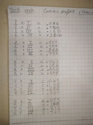
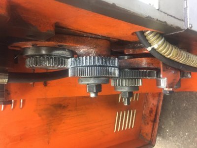
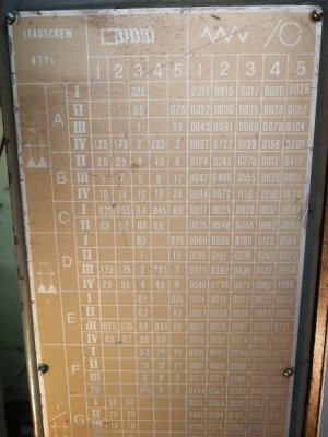
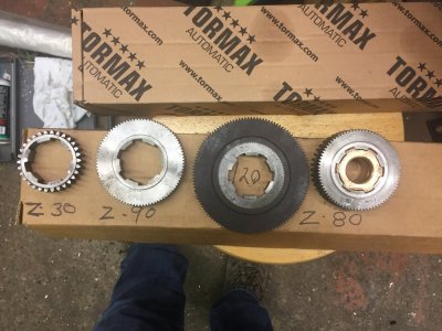
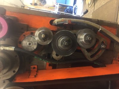
Attached pic of my gear train, I can only cut threads section F 36 thru 3,
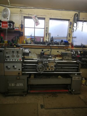
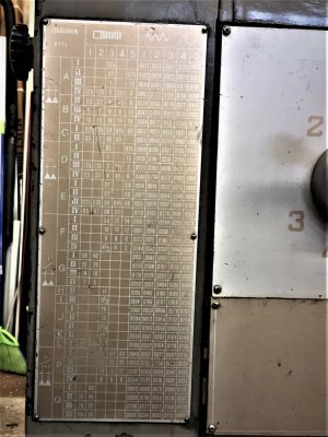
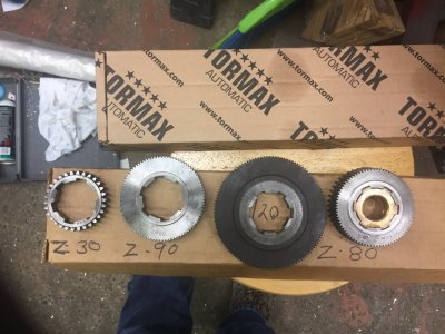
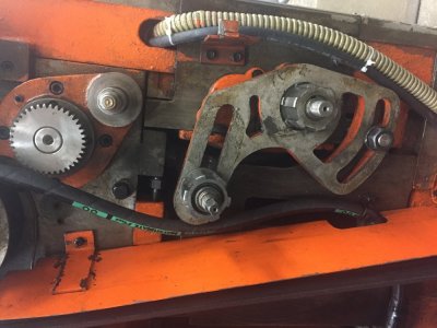
i have zero info for this lathe, my quest is to cut proper change gears for threads and feed listed, doesn't seem to have a lot of options.
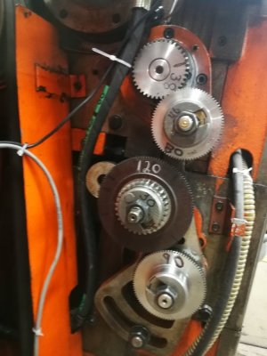
it appears as there are 2 spots for extra gears
"oops all the pic are rotatedView attachment 13206
i have zero info for this lathe, my quest is to cut proper change gears for threads and feed listed, doesn't seem to have a lot of options.
it appears as there are 2 spots for extra gears
"oops all the pic are rotatedView attachment 13206
Attachments
Last edited: