-
Scam Alert. Members are reminded to NOT send money to buy anything. Don't buy things remote and have it shipped - go get it yourself, pay in person, and take your equipment with you. Scammers have burned people on this forum. Urgency, secrecy, excuses, selling for friend, newish members, FUD, are RED FLAGS. A video conference call is not adequate assurance. Face to face interactions are required. Please report suspicions to the forum admins. Stay Safe - anyone can get scammed.
-
Several Regions have held meetups already, but others are being planned or are evaluating the interest. The Calgary Area Meetup is set for Saturday July 12th at 10am. The signup thread is here! Arbutus has also explored interest in a Fraser Valley meetup but it seems members either missed his thread or had other plans. Let him know if you are interested in a meetup later in the year by posting here! Slowpoke is trying to pull together an Ottawa area meetup later this summer. No date has been selected yet, so let him know if you are interested here! We are not aware of any other meetups being planned this year. If you are interested in doing something in your area, let everyone know and make it happen! Meetups are a great way to make new machining friends and get hands on help in your area. Don’t be shy, sign up and come, or plan your own meetup!
You are using an out of date browser. It may not display this or other websites correctly.
You should upgrade or use an alternative browser.
You should upgrade or use an alternative browser.
Another threading question
- Thread starter ShawnR
- Start date
I am going out to try it again on ABS. All I want is a plastic adapter (or aluminum) to stick a mirage tube onto my scope
What a great idea! It would be nice to make an adapter that would take some cheap tubing to make them as long as needed. The biggest problem is keeping them on with recoil.
I find field mirage isn't as big a deal as mirage from barrel heat.
lucsimoneau
Well-Known Member
Just my 2% input here, the website Theoretical Machinist can be tweeked to get the thread dimensions you need - so in this case you are aiming for a M45-0.6 thread which gives a pitch diameter of 44.610/44.503 dimension. This is what you have to measure, either by the 3 wire method or with a thread micrometer. As mentioned, for such a small thread, the angle of tool feed is quite negligable, so the easy way is to feed in perpendicular to the part. Good luck:

Just my 2% input here, the website Theoretical Machinist
Hey Luc, exactly what is a "theoretical machinist'? Seems like an odd combination of words to me.
I see that the website has a French origin. Is this unusual name perhaps an accident of French conversion to English?
Some interesting tools on that website.
Well, look what Shawnee did! 🙂
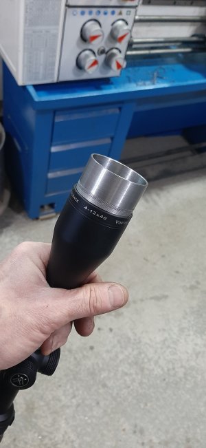
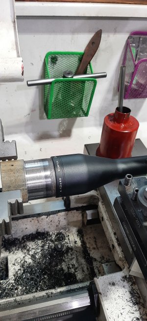
After the crash course in threads from all of you great members, and armed with a better understanding of threads, I headed back to the shop this morning. I had left the setup in the lathe last night when I walked away, so, basically, made a deeper pass. Voila!! Guess I was on the right track but did not really know why.
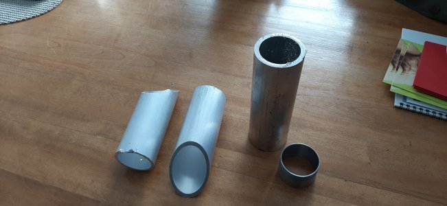
I did a couple more tries in plastic, but still no luck @Susquatch . The issue on that is probably the geometry of my cutting bit. But, I do have a nice piece of Delrin stock so might try that. It is solid 2" so lots of boring, considering how thin I want the wall. Also, I will stop at a local machine shop and try to get a piece of aluminum pipe. I would rather do that. I don't want to be screwing this steel adapter into an aluminum tube for fear of, at some point, ruining the scope threads.
I should add that, on the plastic attempts, I tried straight in instead of advancing the compound. I like it. Will experiment more with that too.
A great learning experience! Thanks everyone!
Attachments
I don't want to be screwing this steel adapter into an aluminum tube for fear of, at some point, ruining the scope threads.
Good plan. Also, don't forget to add a shoulder so the adapter doesn't bottom in the threads. You want it to bottom on a shoulder (often called a register) so it's a nice firm stop.
Duh! that's exactly what I recall doing myself before when I posted that link. Thanks for mentioning. You can use the standard thread dropdowns for convenience or input your own nominal diameter & it calculates all the other stuff.Just my 2% input here, the website Theoretical Machinist can be tweeked to get the thread dimensions you need - so in this case you are aiming for a M45-0.6 thread which gives a pitch diameter of 44.610/44.503 dimension.
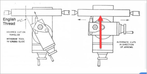
Re the 90-deg or 0-deg it means the exact same thing. You feed the V-profile in perpendicular to the work (which is 90-deg). But some lathes have compound gradations where this equates to 0-deg which is what they reference. But for 'straight in' the compound setting & movement is really irrelevant & not required, in fact should be locked if possible. First you set the tool angle relative to the work. Picture showing an insert which references off a face, or use one of those vee jig things. Then the normal cross slide movement takes care of the rest. Some people have a technique where quickly back out of one or the other (cross slide or compound) as they approach the end of thread. Then rest one of the 2 back to zero. My own preference is detach threading via the engagement lever/ clamshell within the thread relief & only rely on setting a single dimension - the cross dimension. Remember to take out backlash & infeed only, don't back out a bit to line up a gradation. This issue is reduced with a DRO but its still a good habit. Not having a cross slide lock is an accuracy hindrance especially with leadscrew backlash & fine threads. Most of my 'mistakes' on fine threads have been measurement errors tricked by tiny burrs. So I always clean up the thread OD with fine paper on backing stick & clean it, at least as you approach final measurements. And I really like my AliExpress digital thread micrometer. Good value. Switch between inch/metric with a button push. Quickly mike down the length of a thread to confirm no deflection deviation. Way faster than wires (at least for me).
Attachments
lucsimoneau
Well-Known Member
I think the name comes from the fact that all information is based on "theory" vs "practical" information. At the college where I teach mechanical engineering, we add the thread information from Martin's page directly on our 2D drawings created in SolidWorks. This takes out the guess work from our students and is a good source of information.Hey Luc, exactly what is a "theoretical machinist'? Seems like an odd combination of words to me.
I see that the website has a French origin. Is this unusual name perhaps an accident of French conversion to English?
Some interesting tools on that website.
lucsimoneau
Well-Known Member
Here's an example of a non-standard thread:

Playing catchup on the forum, so after reading the first few posts I skimmed the rest, and see you got a fit.
In your original picture, just visually looking I knew you had to go deeper, as the with of the ‘groove’ was much smaller than the flat or what will become crest of the thread.
Most 60 degree thread forms the root or valley of the thread will be the same width as the crest. Same for Acme and quite a few others when you get to know them.
Pitch is the same for any threadform, either the distance from one to the next (Metric) or the number of repeats in an inch. If I’m trying to identify a thread, nd have an imperial pitch gauge (and it seems to match), I sometimes calculate the pitch in decimal inches, then covert to metric. Same for any other measurements. List the info in both side by side, and then start looking at charts. It’s amazing how many ‘threads’ there are out there!!
If I’m trying to identify a thread, nd have an imperial pitch gauge (and it seems to match), I sometimes calculate the pitch in decimal inches, then covert to metric. Same for any other measurements. List the info in both side by side, and then start looking at charts.
This is a good idea. I've been bitten a few times by threads that I thought were metric but were really imperial and vice versa. Two examples right off the cuff were the tool post T-Bolt (prolly a better name for it), and ironically by the tool holder height adjustment post on Aloris style tool holders. That's just two out of many.


