-
Scam Alert. Members are reminded to NOT send money to buy anything. Don't buy things remote and have it shipped - go get it yourself, pay in person, and take your equipment with you. Scammers have burned people on this forum. Urgency, secrecy, excuses, selling for friend, newish members, FUD, are RED FLAGS. A video conference call is not adequate assurance. Face to face interactions are required. Please report suspicions to the forum admins. Stay Safe - anyone can get scammed.
-
Several Regions have held meetups already, but others are being planned or are evaluating the interest. The Calgary Area Meetup is set for Saturday July 12th at 10am. The signup thread is here! Arbutus has also explored interest in a Fraser Valley meetup but it seems members either missed his thread or had other plans. Let him know if you are interested in a meetup later in the year by posting here! Slowpoke is trying to pull together an Ottawa area meetup later this summer. No date has been selected yet, so let him know if you are interested here! We are not aware of any other meetups being planned this year. If you are interested in doing something in your area, let everyone know and make it happen! Meetups are a great way to make new machining friends and get hands on help in your area. Don’t be shy, sign up and come, or plan your own meetup!
You are using an out of date browser. It may not display this or other websites correctly.
You should upgrade or use an alternative browser.
You should upgrade or use an alternative browser.
Another Problem Filled Project
- Thread starter carrdo
- Start date
@jcdammeyer
Here are a couple screen shots from the base directory.
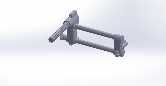
This is the Subassembly 100 series -Base. Opened it as a DWG and it opened the rest of the parts in the directory to complete it.
In Soildworks you need to open this as a part and then select "3D" part. I believe (and may be wrong) that DWG are normally "2D" parts but can be used for "3D" parts.
Solidworks made a .sldprt file for each part in the same directory as it did this.
Here is the left base part opened separately.
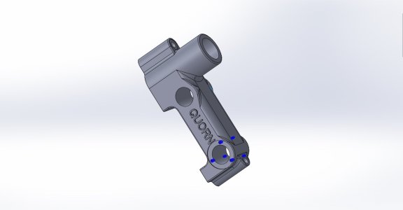
Getting the sketch for these takes a little more work, but not impossible.
(Note: For others trying this these parts are not in the previous file that was posted.)
Here are a couple screen shots from the base directory.

This is the Subassembly 100 series -Base. Opened it as a DWG and it opened the rest of the parts in the directory to complete it.
In Soildworks you need to open this as a part and then select "3D" part. I believe (and may be wrong) that DWG are normally "2D" parts but can be used for "3D" parts.
Solidworks made a .sldprt file for each part in the same directory as it did this.
Here is the left base part opened separately.

Getting the sketch for these takes a little more work, but not impossible.
(Note: For others trying this these parts are not in the previous file that was posted.)
Dan Dubeau
Ultra Member
I could not open or recover it in Mechanical Desktop 2006, nor Rhino V8 either.
Ant chance they are the same as on CAD forums?
 grabcad.com
Or Toms site?
Free CAD Designs, Files & 3D Models | The GrabCAD Community Library
The GrabCAD Library offers millions of free CAD designs, CAD files, and 3D models. Join the GrabCAD Community today to gain access and download!
Or Toms site?
The SLDPRT files in the grabcad I also have and those I can open and edit.Ant chance they are the same as on CAD forums?
Free CAD Designs, Files & 3D Models | The GrabCAD Community Library
The GrabCAD Library offers millions of free CAD designs, CAD files, and 3D models. Join the GrabCAD Community today to gain access and download!grabcad.com
Or Toms site?
Tom's site CAD Drawings is where I got a lot of the zips and for example "500 Spiraling Head Bracket.dwg" is one of the files that Alibre won't open for some reason.
Dan Dubeau
Ultra Member
That's the issue there. They're all referencing each other in the assembly. You must structure them in the right directories as shown in parenthesis. IMO, a pretty dumb way of doing it in this day and age......But I'll prepare for my dressing down from an engineer that knows better.....
I've asked on the Alibre forum why the Raw Castings dwg files don't import.
Hi All,
Working through the last issue.
Again, a lot of the time and effort involved is the preparation work and this time it is no different.
One first has to partially dismantle the tool workhead from the rest of the Quorn and this is no small fiddle. No photos were taken of this.
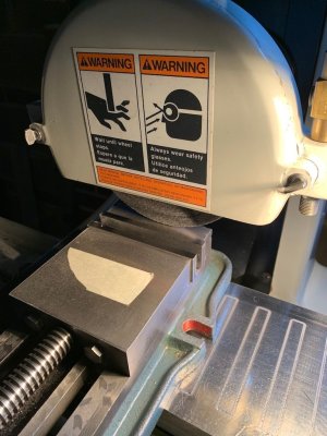
Next, I needed to grind the top of the milling machine vise jaws dead level and equal in height. See photo 222. One has to do this periodically anyway so this was the opportunity.
Next, was to set the main bore of the tool holder boss square when the tool holder base assembly rested on top of the SG milling machine vise jaws as seen in photo 223. A couple of SG spacers needed to be made as well which were dead parallel and square themselves for this setup.
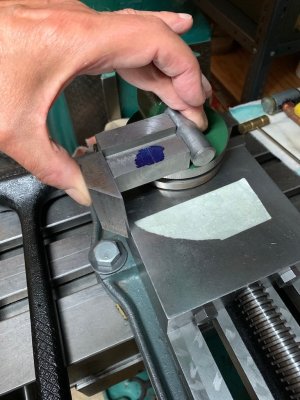
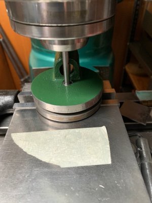
Next, was to precisely locate and center the base bore in the tool holder casting which was achieved using a collet in the spindle of the mill and a straight ground, on size rod. This would be greatly facilitated if the base bore was dead square to the spindle of the mill, hence the need to grind the top of the jaws of the mill vise to achieve this. Photo 224. It goes without saying that the spindle of the mill also needs to be trammed square to the table of the mill.
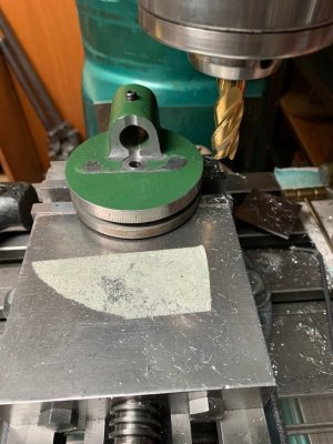
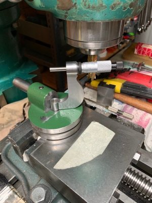
The next operation was to actually cut some metal. The vertical cutout - radial clearance for the radius setting micrometer was achieved through careful plunge milling with a new 9/16" diameter center cutting end mill held in a collet after which the inner face of the tool holder mounting boss was milled square to the bore of the boss as seen in photo 225. This was done as a single (combined) operation.
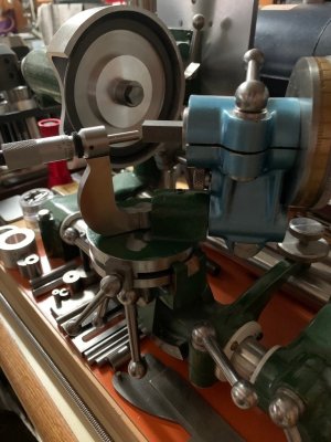
And there it is, photos 226, 227. The radius gauge sits marginally below the centreline of any tool held in the tool holder (in its highest position) which is what I want as the entire radius gauge
assembly can now be raised or lowered slightly to match centre line to centre line to any degree of accuracy needed.


Hehere's the answer: "They appear to be AutoCAD 3D DWG, which Alibre does not support."I've asked on the Alibre forum why the Raw Castings dwg files don't import.
John, I replied to your PM. I did not check here first. These photos are for your private message as I can not attach them to the PM.
@carrdo sorry for sliding into your build thread. Would you prefer if we started another thread?
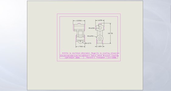
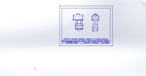
Spiraling head brachet
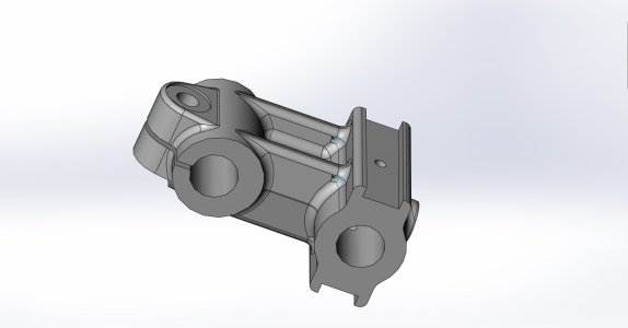
SpiralingHeadBracket
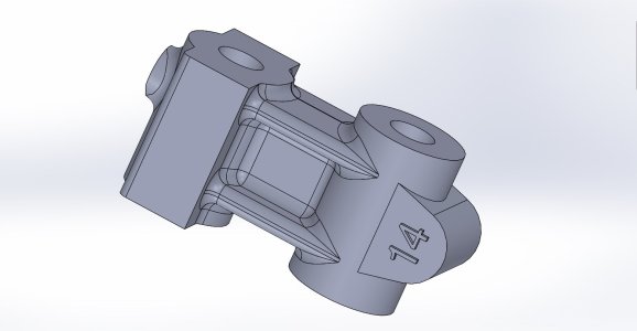
SpiralingHeadBracket2 and SpiralingHeadBracket3 opened in two different methods.
Cheers, P
@carrdo sorry for sliding into your build thread. Would you prefer if we started another thread?
Spiraling head brachet

SpiralingHeadBracket

SpiralingHeadBracket2 and SpiralingHeadBracket3 opened in two different methods.


Cheers, P
Weird how this doesn't match the book at all.John, I replied to your PM. I did not check here first. These photos are for your private message as I can not attach them to the PM.
@carrdo sorry for sliding into your build thread. Would you prefer if we started another thread?
Spiraling head brachet
View attachment 67433
SpiralingHeadBracket
View attachment 67432
SpiralingHeadBracket2 and SpiralingHeadBracket3 opened in two different methods.
View attachment 67430
View attachment 67431
Cheers, P
