• Scam Alert. Members are reminded to NOT send money to buy anything. Don't buy things remote and have it shipped - go get it yourself, pay in person, and take your equipment with you. Scammers have burned people on this forum. Urgency, secrecy, excuses, selling for friend, newish members, FUD, are RED FLAGS. A video conference call is not adequate assurance. Face to face interactions are required. Please report suspicions to the forum admins. Stay Safe - anyone can get scammed.
  • Several Regions have held meetups already, but others are being planned or are evaluating the interest. The Calgary Area Meetup is set for Saturday July 12th at 10am. The signup thread is here! Arbutus has also explored interest in a Fraser Valley meetup but it seems members either missed his thread or had other plans. Let him know if you are interested in a meetup later in the year by posting here! Slowpoke is trying to pull together an Ottawa area meetup later this summer. No date has been selected yet, so let him know if you are interested here! We are not aware of any other meetups being planned this year. If you are interested in doing something in your area, let everyone know and make it happen! Meetups are a great way to make new machining friends and get hands on help in your area. Don’t be shy, sign up and come, or plan your own meetup!

Another Problem Filled Project

carrdo

Super User
Hi All,

This seems to be my fate. Everything which I take on seems to want to fight me to the bitter end. This is no exception. Probably because I am my own worst enemy being too perfectionist.

This time it is constructing an accessory for the Quorn T&C grinder which, in itself, has been one of the biggest boondoggles of my machining life. But at the time, many decades ago, there was nothing like it commercially available on the market.

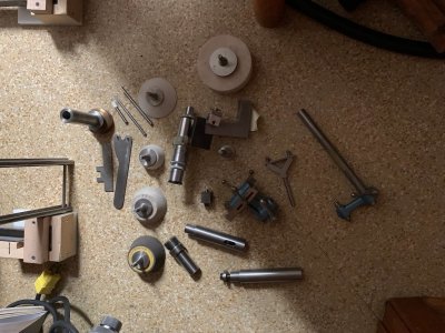
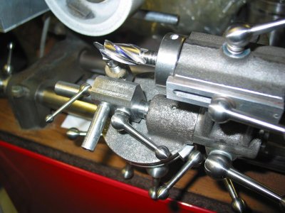
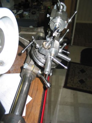
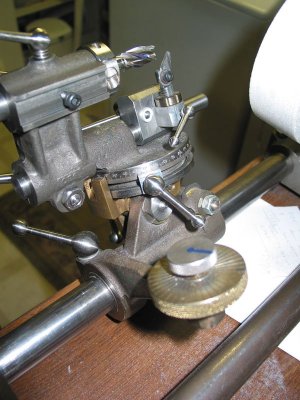
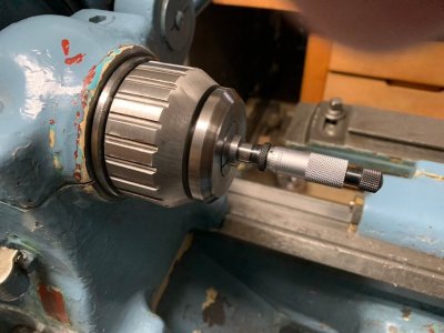
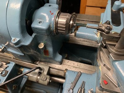
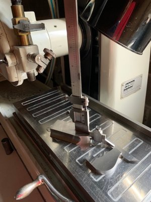
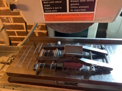
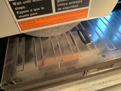
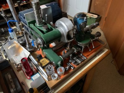
As one knows with any T&C grinder, it is only as useful as the number of accessories which it has and this is also true of the Quorn. The first photo (186) shows only a few of the extras made to date. And there are a few dozen accessories needed to make it the universal T&C grinder which it has become over the decades. Historically, it was never designed for this function but it has been adapted to do many other things by enterprising hobbyist and home shop constructors. As it was intended for model making work only, it will never be useful for any commercial work as are the much larger and heavier industrial grinders. But to function properly, it has to be made to the same exacting geometry, tolerances and fits of its larger counterparts.

So, what was needed to be made?

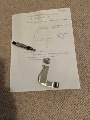
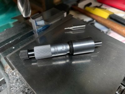
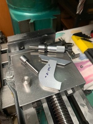
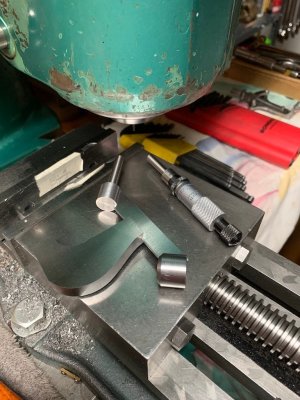
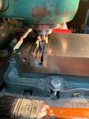
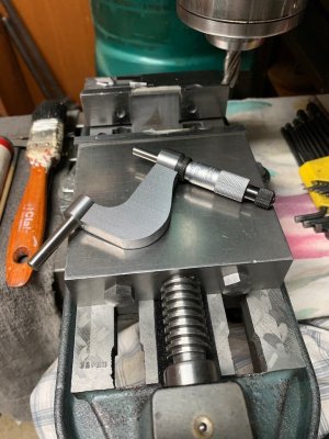
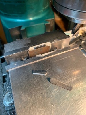
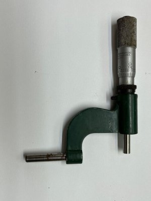
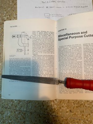
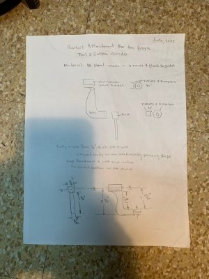
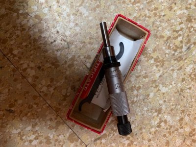
Photo 187, taken from the web, shows a very high quality micrometer radius setting gauge which I intended to make also. I forgot to detail where I got the photo from so my apologies to the original builder. Photo 188, which is taken from the Quorn construction book, shows the original drawing of this radius setting micrometer gauge. Photo 190 shows the micrometer head purchased for this purpose. Note that it is a bit different to the micrometer head shown on the Quorn drawing and the other shop made micrometer head. This is important but I didn't realize how important. Finally, photo 189 is the sketch I made of the basic unit parts.

The stage was now set for all of the problems which followed.

to be continued.
 

Attachments

  • 186 The Quorn T&C Grinder with  the Accessories Made to Date.jpg
    186 The Quorn T&C Grinder with the Accessories Made to Date.jpg
    165 KB · Views: 62
  • 187 A Home Shop Made  Radius Setting Micrometer for the Quorn.jpg
    187 A Home Shop Made Radius Setting Micrometer for the Quorn.jpg
    35.2 KB · Views: 33
  • 188 The Drawing of the Radius Setting Micrometer in the Quorn Book.jpg
    188 The Drawing of the Radius Setting Micrometer in the Quorn Book.jpg
    190.3 KB · Views: 42
  • 189 The Sketch Of What I Wanted to Make.jpg
    189 The Sketch Of What I Wanted to Make.jpg
    135.6 KB · Views: 37
  • 190 The Micrometer Head to Be Used.jpg
    190 The Micrometer Head to Be Used.jpg
    161 KB · Views: 59
A couple of years ago, I had the loan of a Quorn for a couple of months. I found it to be the most complex, fiddly, obnoxious, cantankerous piece of--well, let's say machinery--I have ever encountered.
By the time it was finished with me, I was ready to beg the owner to take it back. In fact, I would have paid him to do so, but, amazingly, he accepted it with equanimity. It seems he liked it.
Oh, well. As they say, de gustibus non disputandumst.
 
Hi All,

This seems to be my fate. Everything which I take on seems to want to fight me to the bitter end. This is no exception. Probably because I am my own worst enemy being too perfectionist.

This time it is constructing an accessory for the Quorn T&C grinder which, in itself, has been one of the biggest boondoggles of my machining life.
Oh great, I’m just starting my Quorn. “Fortunately” I’m not constrained by perfectionism so perhaps it won’t be too bad.

I have a few questions though. What are the accessories you mention? What are they for and which are the most useful?
I did find a few builders who mentioned making the bed a bit longer. Did you go with the standard length? Your thoughts?

Thanks
John
 
Been thinking about making a multi function sharpening station like the Quorn or Bonnelle as next winters indoor project. Despite the delays, I've had a lot of fun and enjoyment designing/building my belt grinder, so would like to do the same process with a grinder station. I only have a vague familiarity with the quorn and Bonnelle and their inherent shortcomings, but will do some more research in the coming months, and keep an eye on your progress as you finish building it. Being able to sharpen (almost) all the cutting tools one uses in the shop is a pretty handy capability.
 
Hi John,

I will try to answer your questions but will be realistic about everything.

Building the Quorn is a major commitment in time and effort. It is not just about making the parts but every operation often involves making the secondary fixtures and tooling before one can even start. Often, one can find a part constructed or a fully finished unit in the UK or in the US so this is an option. But don't buy junk, it has to be at least very well made. There are now also other options which are easier to make or buy.

My Quorn is one of the early ones, a MKI with additions to being a near MKII having the standard bed length. I wanted it to be able to basically sharpen end mills and for that the standard bed length works just fine.

Now, many claims have been made about the Quorn and what it can do but I have actually seen only a handful of people who have actually done some of the things claimed for it. I will add some additional photos shortly of one such person, our current TSME President, Wolfgang Habichier who uses his Quorn to actually sharpen the spiral cutting edges on end mills in addition to just the ends of end mills which is much easier. But to do this he made some additional modifications which I will show. Also, even with all of the fancy accessories, additions, modifications, etc., because the unit is so small and "light" one needs to develop a sensitive touch/technique to be successful so some practice is in order no matter what you end up with.

Before you start, I would suggest that you obtain a copy of the Quorn construction book as shown in photo 202. One can find used copies on ebay or buy new from the UK. Also, I would suggest that you join the Quorn Owners Group (Groups IO). Just google Quorn Owners Group. I am there also. Thirdly, and I will throw this out for beginners, the book Tool & Cutter Sharpening (for home machinists) by Harold Hall is an excellent starting reference.

Concerning the workhead, my unit uses #2 Morse taper collets as seen in photo 203. It will hold work up to 1/2" in diameter. Later versions use the more popular ER collet series and one can get an even larger workhead which will hold up to 1" diameter pieces. This may or may not be a concern but if it is the Quorn Owners Group shows lots of options.

Photo 201 shows what I have for accessories to date. Most of them, other than for the workholding arbors, I have not used. However each grinding wheel needs to have its own custom fitted wheel flange, mounting arbor and paper washer and since I have over a dozen different grinding wheels, not all of which are shown... In addition, it is desirable to have each of these wheel assemblies at least statically balanced and possibly dynamically balanced as well but the later is not possible in a home shop or without specialized equipment.
 

Attachments

  • 203.jpg
    203.jpg
    120.7 KB · Views: 13
  • 202.jpg
    202.jpg
    163.9 KB · Views: 10
  • 201.jpg
    201.jpg
    182.8 KB · Views: 9
Hi All,

Photos of a modified Quorn by Wolfgang Habichier given at a TSME demonstration. All credit for this is given to Wolfgang - it was impressive. Notice his technique of blueing the spiral cutting edges of the end mill before starting to sharpen them.
 

Attachments

  • 75 Wolfgang Habicher's Quorn T&C Grinder Setup for Sharpening the Spirial Flutes on an End Mill.jpg
    75 Wolfgang Habicher's Quorn T&C Grinder Setup for Sharpening the Spirial Flutes on an End Mill.jpg
    97.9 KB · Views: 9
  • 77 The Modified Tooth Rest.jpg
    77 The Modified Tooth Rest.jpg
    86.3 KB · Views: 11
  • 78 Wolfgang's Quorn Modified Tooth Rest Assembly.jpg
    78 Wolfgang's Quorn Modified Tooth Rest Assembly.jpg
    71.3 KB · Views: 12
  • 79 The Modified Tooth Rest.jpg
    79 The Modified Tooth Rest.jpg
    95.6 KB · Views: 12
  • 80 The Modified Tooth Rest.jpg
    80 The Modified Tooth Rest.jpg
    80.8 KB · Views: 13
Last edited:
@carrdo Thanks for the additional information. My “sort of” Quorn is a a learning project with hope for something useful when it’s done. I’m doing my own castings in aluminum although I suspect the wheel head assembly will end up being steel weldments. I’ve already found there are almost as many jigs as finished parts. I’m looking forward to the ball handles but a ball turner will be needed first!

Cheers
John
 
Hi All,

So, on with how I got myself into trouble again.

If you look at the Quorn book drawing of the micrometer radius gauge again, it shows the micrometer head, when set at the 0,0 thimble position, the end of the micrometer spindle projects out exactly 5/8" from the vertical face of the radius gauge body. The vertical face of the radius gauge body is a very important reference surface which, initially, I didn't realize how important it was. And at 5/8" stick out from this vertical face, the end face of the micrometer spindle is exactly on the vertical centreline of the rotating pin which sits down into the base of the rotating workhead giving it, in this position, a zero radius. The micrometer head itself has a 1/2" travel ( = 0"- 1/2" radius) allowing one to sharpen up to 1" diameter ball nose end mills as stated in the Quorn book.

However, with the micrometer head which I am using the spindle stick out was 3/4" not 5/8" when the micrometer spindle was set to 0,0.

None of the above even entered my head when I happily started machining all of the bits and pieces and got to the point shown in photo 193.

I unfortunately didn't take any photos up to this point but basically the body of the gauge was laid out on a 1/2" thick piece of hot rolled steel to an aesthetically pleasing shape and then by a combination of milling, belt sanding and bandsawing the gauge body shape was produced as shown in the photo.

Initially, I did some thinking about how the two round end cylinder pieces could be securely attached to the body of the gauge such as by pinning, glueing, silver soldering, etc. Photo 191 shows the ball milling of the ends of the body piece to have a curved saddle which would end up supporting and aligning the two round end pieces.

It must be realized also that to have a correctly functioning radius gauge everything has to be aligned dead square, centered, and must be straight and parallel, etc. So all of this had to be carefully checked as one proceeds. Since I don't have any digital or electronic aids, one has to go back to basics of mechanical checking, testing and checking again.

It was at this point that the first trial fitting to the Quorn workhead, said very loudly that something was wrong as I was nowhere near what the Quorn book drawing was showing. Oh, dear.

to be continued.
 

Attachments

  • 193 The Partially (incorrectly) Made Micrometer Radius Setting Gauge Parts.jpg
    193 The Partially (incorrectly) Made Micrometer Radius Setting Gauge Parts.jpg
    137.3 KB · Views: 8
  • 191 Milling A Curved Saddle on the Body of the Radius Setting Micrometer.jpg
    191 Milling A Curved Saddle on the Body of the Radius Setting Micrometer.jpg
    148.6 KB · Views: 9
  • 194 Checking Square on the Micrometer Setting Gauge Body Part.jpg
    194 Checking Square on the Micrometer Setting Gauge Body Part.jpg
    151.2 KB · Views: 9
Hi All,

Pushing on.

After realizing the problem which had been created, there was nothing left to do but to try and fix it. Fortunately, the radius gauge body was too long in both axis, so I had material left to make corrections.

Adjusting the radius gauge vertically is not that difficult as it sits on the rotating pin in the reamed centre hole in the base of the rotating workhead which is adjustable vertically. The radius gauge body height can be shortened and then the entire gauge assembly adjusted up and down on the pin so the centre line of the micrometer spindle becomes exactly coincident with the centre line of the toolholder arbor. Of course the setup has to be exact to maintain square and without tilt of any kind.

Achieving the critical horizontal offset, which in my case, now became 3/4" rather than the original 5/8" was more demanding. Photo 192 shows the setup used to achieve this. The vertical inside machined face of the radius body was set dead level in the vise of the mill (by indicating) and the round micrometer plug set in the saddle of the upturned leg of the radius body. The measured height over the top of the plug minus half the plug diameter itself minus the height of the horizontal machined reference surface gave the horizontal offset. In the end this needed to be a shaving operation with a new 5/8" dia. ball end mill. But luck was on my side this time as the final calculations indicated I had achieved the 3/4" offset to much better than 0.0005", I would hazard a guess of 0.0002" - 0.0003".

Next up was the internal boring of the micrometer plug to hold the micrometer head. This was another "zero clearance" (all collet work) precision boring operation done on my old WWII 13" SB small bore toolroom lathe. This lathe has seen a lot of use and some abuse before I ever got it but if one is careful and your tools are really sharp and I mean sharp, you can still precision bore to "tenths" with it. It ended up as a smooth hard push fit without any shake at all so again probably it has only 0.0002" clearance on the bore diameter. It also had to have a step bored in with the depth being controlled by the micrometer depth stop partially seen in photo 197.

to be continued.
 

Attachments

  • 199 The Partially Finished Micrometer Head Holder.jpg
    199 The Partially Finished Micrometer Head Holder.jpg
    112.5 KB · Views: 10
  • 198 A First Class Precision Fit.jpg
    198 A First Class Precision Fit.jpg
    108.2 KB · Views: 11
  • 197 Precision Boring the Setting Micrometer Holder.jpg
    197 Precision Boring the Setting Micrometer Holder.jpg
    162.1 KB · Views: 10
  • 192 Checking a Critical Dimension.jpg
    192 Checking a Critical Dimension.jpg
    147.3 KB · Views: 9
Hi All,

The next problem dealt with was how to attach and secure the two end plugs to the radius gauge body.

Once the radius gauge body had been secured square in the vise, the cross slide of the mill was locked to ensure all subsequent saddle radiusing operations were carried out in the same plane, the part only being rotated against the fixed jaw of the vise to gain access to both ends. In addition, when the locking operation was carried out it was also in the same plane without changing any setting being changed. The radius body was still oversize, on thickness, at this point so I still had some extra material to work with.

The strongest most secure method would have been to silver solder the parts together because hot rolled steel is an ideal steel for silver soldering forming both an aesthetically pleasing and structurally sound joint. However, because it requires heating the parts red hot ( I find the new cadmium free silver solders require heating to an even hotter pale straw/yellow heat to flow freely), there could be some residual distortion so I went back to my old tried and tested ways of doing things the hard way again.

What I came up with was a combination of precision keying and glueing the parts together. Photo 200 shows the milling of a 1/16" wide and deep key slot in each end of the radius gauge body. It was slow delicate work taking only a 0.002" DOC per pass and running the mill spindle at the fastest speed the VFD would allow but the operation proceeded without incident ensuring the slot was dead central on the saddle curve.

To further ensure everything was centered thickness wise, a dummy close fitting surface ground spacer piece as seen in photos 201 and 203 was made to a tap fit in the 1/16" keyway slots. The body of the radius gauge was then ground equally down on each side achieving this by grinding a body side, checking the height over the spacer piece as shown in photo 201, then flipping the part over, measuring the height over the spacer piece again and grinding each side in turn until both height gauge readings were dead equal.

Photo 203 shows the parts as of now. The micrometer holder plug has been shortened in line with the needed micrometer spindle stick out and bevelled next to the micrometer spindle thumb lock to give better finger access to the lock.

to be continued.
 

Attachments

  • 200 Milling the One Sixteenth Inch Central Key Slot in the Setting Gauge Body.jpg
    200 Milling the One Sixteenth Inch Central Key Slot in the Setting Gauge Body.jpg
    136.3 KB · Views: 8
  • 201 Grinding Down and Height Checking Each Side of the Radius Gauge Body to Ensure the Keyway ...jpg
    201 Grinding Down and Height Checking Each Side of the Radius Gauge Body to Ensure the Keyway ...jpg
    142 KB · Views: 9
  • 203 All the Parts for Assembly.jpg
    203 All the Parts for Assembly.jpg
    139.6 KB · Views: 8
Been thinking about making a multi function sharpening station like the Quorn or Bonnelle as next winters indoor project. Despite the delays, I've had a lot of fun and enjoyment designing/building my belt grinder, so would like to do the same process with a grinder station. I only have a vague familiarity with the quorn and Bonnelle and their inherent shortcomings, but will do some more research in the coming months, and keep an eye on your progress as you finish building it. Being able to sharpen (almost) all the cutting tools one uses in the shop is a pretty handy capability.
I would be more inclined to use a 1200 grit belt on the sander and spend a bit of time making a "end mill' attachment for it...buddy of mine made a drill bit sharpening jig for his belt sander and man he can do a nice job on any bit from 1/8 up to 1 1/4. every bit he has sharpened for me has cut an exact same spiral from both lips
 
One of the attachments I had been sketching out for my belt grinder was a drill sharpening one. I'd also thought about cutter grinding too. It's on the wish list, and I'll experiment more when I get the main grinder completely finished and functioning which is close. None of those made it past the 2d sketching phase yet, so I had no real time invested, but they are possible. Now that I have the main grinder body re modeled again, i can start with the accessories again.

The one thing that might not be possible is doing the ends, as the belt edges are not consistent enough for that, certainly not as defined as a dressed edge on a wheel, but I have something I want to try to mitigate that. Making a hard wheel arbor belt driven off the drive wheel is a future plan too. I miss being able to sharpen single lip cutters properly.....

There are a lot of untapped possibilities with a belt grinder and the wide variety of abrasives available. It's a good base for attachments, but an actual grinding wheel is still necessary for some operations. Combining the function of the two would be pretty great though......I have lots of ideas.....:D. More ideas than time and money lol.
 
Back
Top