-
Scam Alert. Members are reminded to NOT send money to buy anything. Don't buy things remote and have it shipped - go get it yourself, pay in person, and take your equipment with you. Scammers have burned people on this forum. Urgency, secrecy, excuses, selling for friend, newish members, FUD, are RED FLAGS. A video conference call is not adequate assurance. Face to face interactions are required. Please report suspicions to the forum admins. Stay Safe - anyone can get scammed.
-
Several Regions have held meetups already, but others are being planned or are evaluating the interest. The Calgary Area Meetup is set for Saturday July 12th at 10am. The signup thread is here! Arbutus has also explored interest in a Fraser Valley meetup but it seems members either missed his thread or had other plans. Let him know if you are interested in a meetup later in the year by posting here! Slowpoke is trying to pull together an Ottawa area meetup later this summer. No date has been selected yet, so let him know if you are interested here! We are not aware of any other meetups being planned this year. If you are interested in doing something in your area, let everyone know and make it happen! Meetups are a great way to make new machining friends and get hands on help in your area. Don’t be shy, sign up and come, or plan your own meetup!
You are using an out of date browser. It may not display this or other websites correctly.
You should upgrade or use an alternative browser.
You should upgrade or use an alternative browser.
An appetiser, 74 TX650 rebuid.
- Thread starter toglhot
- Start date
Wheels.
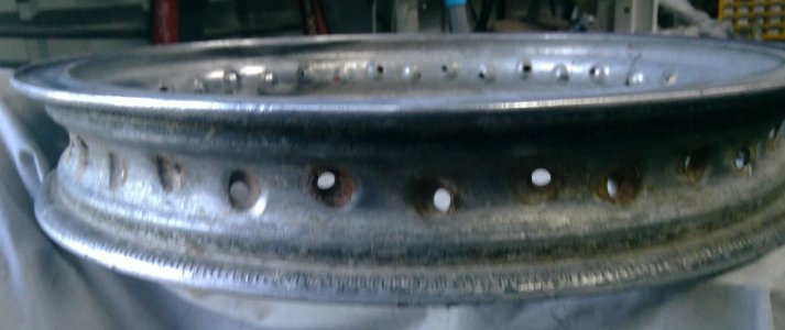
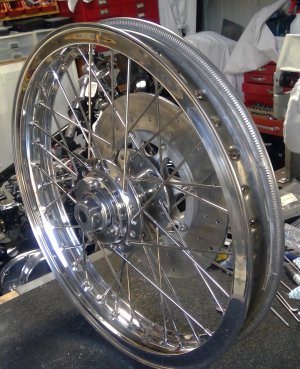
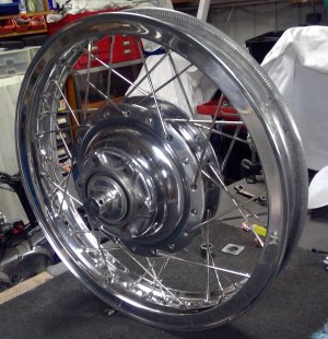
Wheels can make a bike. The TX650 came fitted with alloy wheels, also included were a set of spoked wheels, so, they got the nod. They were in pretty crook shape, the PO obviously had no tyre levers, so used hammers, screwdriver and whatever else he had lying around. The results were not pretty: deep gouges, and scratches on the rims. Hubs were in better shape, although both were badly oxidised and pitted,
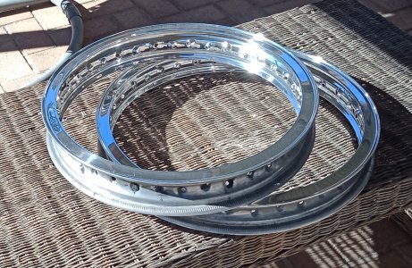
I wasn't sure if I could restore the rims, but gave it a shot anyway and they came up pretty good. I ground the edge of the rim down with an angle grinder fitted with 240 grit disks, the outer walls of the rims were ground with nylon fibre wheels fitted in the angle grinder and the inner section ground with a shaped nylon fibre wheel on an 8"bench grinder converted specifically for polishing.
When all the smoothing was done I polished using a sisal wheel and black compound, then a sewn cloth wheel and white compound, then a loose leaf with white compound, finishing off with a swansdown loose leaf and green compound. There are still a few marks I couldn't get out as they were just too deep, but all in all I was quite pleased with the result.
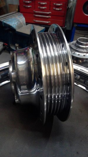
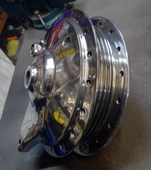
Next came the hubs. I mounted the rear hub on the lathe first and trued up the flanges, then removed the casting bridges between the fins, trued the fins and then poished the hub and brake backing plate. The rear hub came up extremey well, very pleased with the result.
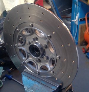
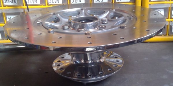
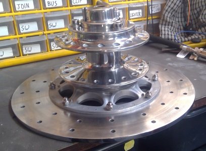
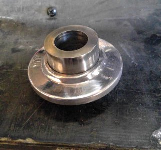
Next came the front hub. Same story, mounted it on the lathe, trued the flanges and turned down the casting bridges between flanges so I could get a mop in deep enough to polish. Again came up pretty good with a bit of a polish.
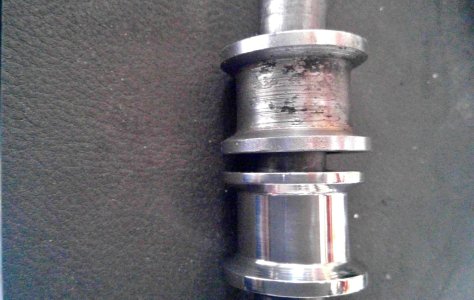
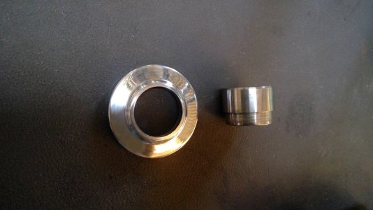
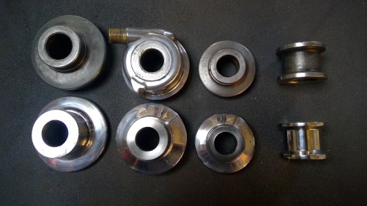
next were the spacers. These were looking a little shabby, so I turned up new spacers from some stainless stock, turned up some dust covers from aluminium stock, pressed then together and poished. The front wheel has monts both side of the hub for twin disks, but I'll only be using a single, so I discarded the rusted cover that covered the left side mounts and fav=bbed an aluminium plate to cover the mounting holes.
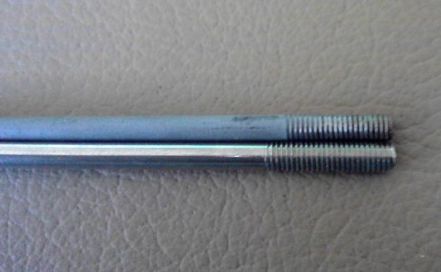
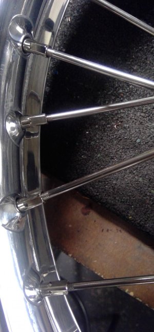
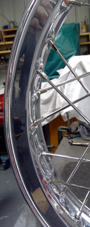
Then I contacted the largest XS650 bits supplier in OZ for some stainles spokes, he ony had front spoke so I ordered them. The spokes turned up and I laced the wheels. Not impressed at all, the threads on the spokes was too long, so when laced, trued centred and torqued there was around 3mm of thread showing before the nipple on every spoke. I took a couple of spokes out and sure enough the spokes were the same length a the stock spokes but the thread extended too far down the spoke, about another 3mm. I compained to the seller,t all I got in return was a series of abusive texts and emails. He informed me his 'profesional' wheel builder said that was acceptable???
Rather than buy spokes from the same seller and have the same problem, I ordered some stainless spokes from Heidens in the Netherlands, same price, just took a little longer to get here. They arrived and I laced the rear wheel, trued it, centred it and torqued the nipples. Perfect, not a single bit of thread showing. I took a picture, sent it to the OZ supplier telling him this is what it should look like. Not surprisingly I got not no reply.
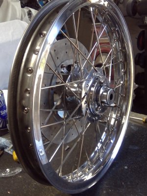
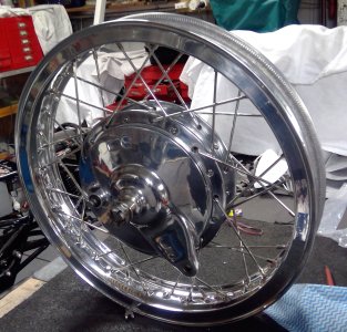
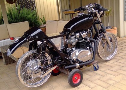
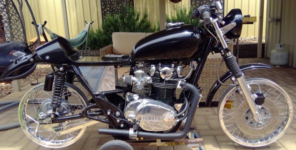
Last job was to polish the ake backing plate. That done, I fitted new bearings, and fitted the wheels - magic, you just can't beat nice hiny spoked wheels. But I do cringe whenever I look at the front wheel .
Wheels can make a bike. The TX650 came fitted with alloy wheels, also included were a set of spoked wheels, so, they got the nod. They were in pretty crook shape, the PO obviously had no tyre levers, so used hammers, screwdriver and whatever else he had lying around. The results were not pretty: deep gouges, and scratches on the rims. Hubs were in better shape, although both were badly oxidised and pitted,
I wasn't sure if I could restore the rims, but gave it a shot anyway and they came up pretty good. I ground the edge of the rim down with an angle grinder fitted with 240 grit disks, the outer walls of the rims were ground with nylon fibre wheels fitted in the angle grinder and the inner section ground with a shaped nylon fibre wheel on an 8"bench grinder converted specifically for polishing.
When all the smoothing was done I polished using a sisal wheel and black compound, then a sewn cloth wheel and white compound, then a loose leaf with white compound, finishing off with a swansdown loose leaf and green compound. There are still a few marks I couldn't get out as they were just too deep, but all in all I was quite pleased with the result.
Next came the hubs. I mounted the rear hub on the lathe first and trued up the flanges, then removed the casting bridges between the fins, trued the fins and then poished the hub and brake backing plate. The rear hub came up extremey well, very pleased with the result.
Next came the front hub. Same story, mounted it on the lathe, trued the flanges and turned down the casting bridges between flanges so I could get a mop in deep enough to polish. Again came up pretty good with a bit of a polish.
next were the spacers. These were looking a little shabby, so I turned up new spacers from some stainless stock, turned up some dust covers from aluminium stock, pressed then together and poished. The front wheel has monts both side of the hub for twin disks, but I'll only be using a single, so I discarded the rusted cover that covered the left side mounts and fav=bbed an aluminium plate to cover the mounting holes.
Then I contacted the largest XS650 bits supplier in OZ for some stainles spokes, he ony had front spoke so I ordered them. The spokes turned up and I laced the wheels. Not impressed at all, the threads on the spokes was too long, so when laced, trued centred and torqued there was around 3mm of thread showing before the nipple on every spoke. I took a couple of spokes out and sure enough the spokes were the same length a the stock spokes but the thread extended too far down the spoke, about another 3mm. I compained to the seller,t all I got in return was a series of abusive texts and emails. He informed me his 'profesional' wheel builder said that was acceptable???
Rather than buy spokes from the same seller and have the same problem, I ordered some stainless spokes from Heidens in the Netherlands, same price, just took a little longer to get here. They arrived and I laced the rear wheel, trued it, centred it and torqued the nipples. Perfect, not a single bit of thread showing. I took a picture, sent it to the OZ supplier telling him this is what it should look like. Not surprisingly I got not no reply.
Last job was to polish the ake backing plate. That done, I fitted new bearings, and fitted the wheels - magic, you just can't beat nice hiny spoked wheels. But I do cringe whenever I look at the front wheel .
Attachments
-
 dirtyrim.jpg155.1 KB · Views: 16
 -
 WIN_20211031_18_18_14_Pro.jpg273.3 KB · Views: 10
 -
 front spoke close up.jpg224 KB · Views: 11
 -
 front 2.jpg401.3 KB · Views: 11
 -
 front 1.jpg521.8 KB · Views: 10
 -
 fronthub disk side.jpg253.3 KB · Views: 11
 -
 fronthub7.jpg191.1 KB · Views: 12
 -
 fronthuband disk.jpg166.1 KB · Views: 13
 -
 rearhub1.jpg239 KB · Views: 12
 -
 rear hub1.jpg53.6 KB · Views: 12
 -
 2 polished rims.jpg296.9 KB · Views: 15
 -
 spacer2.jpg336.7 KB · Views: 10
 -
 spacer.jpg229.2 KB · Views: 10
 -
 spacers.jpg324.7 KB · Views: 10
 -
 spacer4.jpg557.1 KB · Views: 10
 -
 rear brake side 2.jpg573.8 KB · Views: 10
 -
 rear sprocket side 2.jpg497.5 KB · Views: 11
 -
 rear side spoke close up.jpg261.3 KB · Views: 14
 -
 right rear.jpg596.5 KB · Views: 13
 -
 right side.jpg370 KB · Views: 18
Last edited:
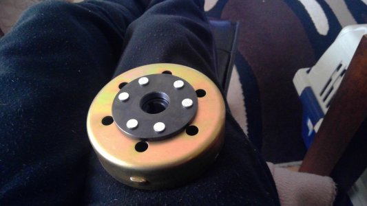
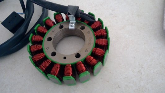
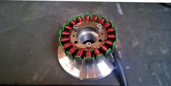
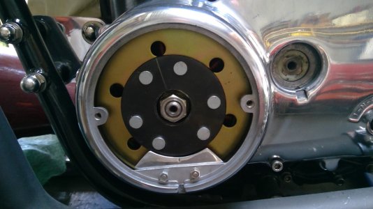
I've done a number of mods for this bike, this is the permanent Magnet Aternator conversion I did.
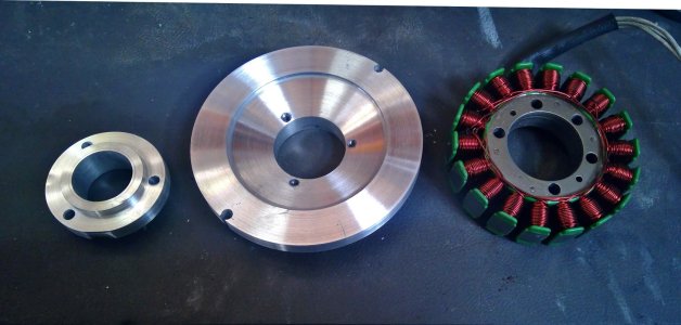
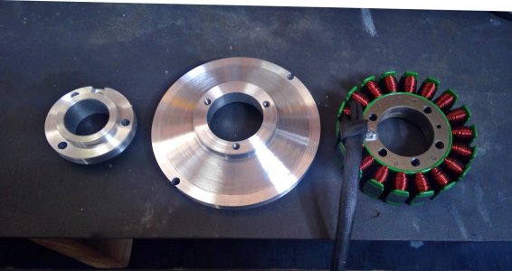
You can buy a kit, but the $$$ are frightening, so, I hunted around for stators and rotors that woud fit, bought a new stator and reg/rec for an XV and a rotor for a Banshee all for $130, then turned up a mount to fit the stator to the XS crankcase.
In fitting the new PMA aternator it's important to fit the stator in the correct position, ie, central to the rotor's magnetic fied. So, I mounted the stator inside the rotor and attached the rotor to the crankshaft and took some measurements. Then I spun up a mount to fit. I didn't have a sab of auminium thick enough to make it from one piece, so, turned up a two piece mount to get the correct height, about 40mm from memory.
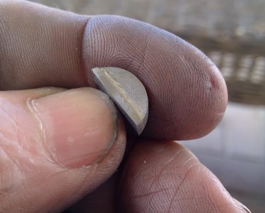
While the rotor fits the XS crank, the woodruff keys are a different thickness, so, I stepped a 6mm woodruff down to 5mm only to find the diameter of the woodruff didn't match the keyway in the crank, so I turned up some stock to the required diameter, cut it in half, stepped it and then shaved the top off the key until the rotor fitted.
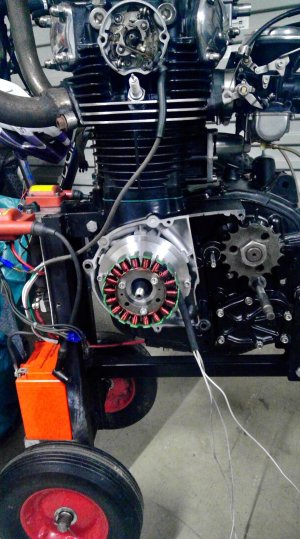
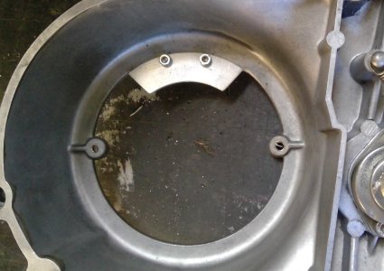
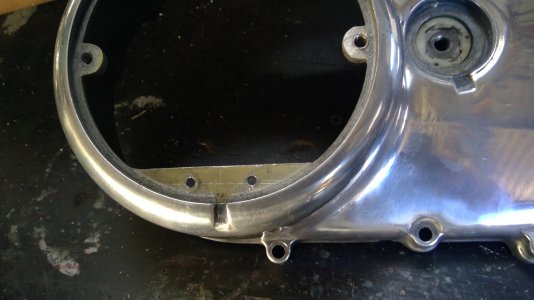
There were marks on the original rotor for timing purposes, however, the Banshee rotor didn't have any, so, I fitted the original alternator again, timed the engine, removed the alternator and fitted the new one. I then made a curved timing plate, fitted it to the left side cover and scribed lines on the rotor and plate.
All that remained to be done was fit the rec/reg, behind the battery carrier on an auminium bracket I made up. That done, I routed the wires through, fitted modular plugs to the regulator and alternator leads and snapped them together.
The stock XS 650 alternator is a brushed unit, so similar to a car's alternator. However, it has a very low output: zero at idle and rising with revs, resulting in a flat battery with all the stopping and starting you do when buiding a bike. A PMA has a 14.4v output from ide right through to max revs, so, no more flat battery,
You can buy a kit, but the $$$ are frightening, so, I hunted around for stators and rotors that woud fit, bought a new stator and reg/rec for an XV and a rotor for a Banshee all for $130, then turned up a mount to fit the stator to the XS crankcase.
In fitting the new PMA aternator it's important to fit the stator in the correct position, ie, central to the rotor's magnetic fied. So, I mounted the stator inside the rotor and attached the rotor to the crankshaft and took some measurements. Then I spun up a mount to fit. I didn't have a sab of auminium thick enough to make it from one piece, so, turned up a two piece mount to get the correct height, about 40mm from memory.
While the rotor fits the XS crank, the woodruff keys are a different thickness, so, I stepped a 6mm woodruff down to 5mm only to find the diameter of the woodruff didn't match the keyway in the crank, so I turned up some stock to the required diameter, cut it in half, stepped it and then shaved the top off the key until the rotor fitted.
There were marks on the original rotor for timing purposes, however, the Banshee rotor didn't have any, so, I fitted the original alternator again, timed the engine, removed the alternator and fitted the new one. I then made a curved timing plate, fitted it to the left side cover and scribed lines on the rotor and plate.
All that remained to be done was fit the rec/reg, behind the battery carrier on an auminium bracket I made up. That done, I routed the wires through, fitted modular plugs to the regulator and alternator leads and snapped them together.
The stock XS 650 alternator is a brushed unit, so similar to a car's alternator. However, it has a very low output: zero at idle and rising with revs, resulting in a flat battery with all the stopping and starting you do when buiding a bike. A PMA has a 14.4v output from ide right through to max revs, so, no more flat battery,
Attachments
-
 rotor 2.jpg184.1 KB · Views: 11
 -
 stator.jpg223.5 KB · Views: 10
 -
 118767751_3567911763254266_5112981845750737633_n.jpg184.8 KB · Views: 10
 -
 118768290_2796583297268365_6752452443242133433_n.jpg139.1 KB · Views: 10
 -
 118716381_2796583790601649_4983637849449141056_n.jpg151.5 KB · Views: 9
 -
 118767888_2796584063934955_6356803461352077540_n.jpg390.9 KB · Views: 11
 -
 timing pointer1.jpg190.8 KB · Views: 11
 -
 timming pointer from inside cover.jpg259 KB · Views: 10
 -
 timing pointer in cover.jpg209.5 KB · Views: 10
 -
 163513280_2968069180119775_3874559522104470106_n.jpg223.6 KB · Views: 11
 -
 woodruff3.jpg283.7 KB · Views: 11
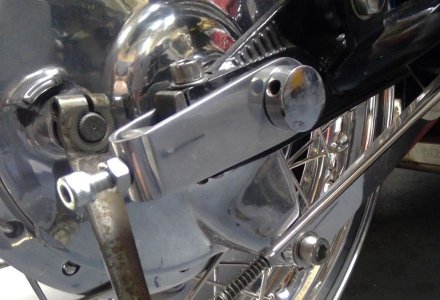
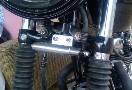
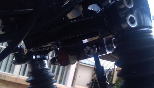
Experiments with chain adjusters.
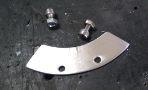
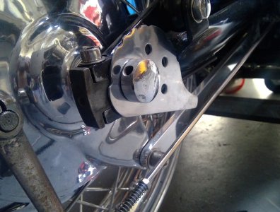
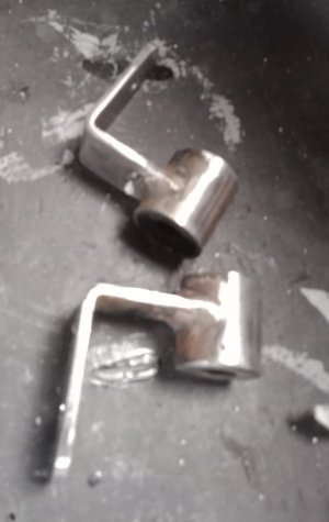
The adjusters on the TX were rusted, so I decided to made some new ones. My first thought was to make snail cams, as they provide a means of aligning the wheels without resorting to the use strings and straight edges. But they, being quite large, were just plain ugly, so they went in the bin.
Next I tried a fabricated one, bent around a 12 mm stainless nut I turned up, but, I just didn't ike the look of that one, so, it too went in the bin.
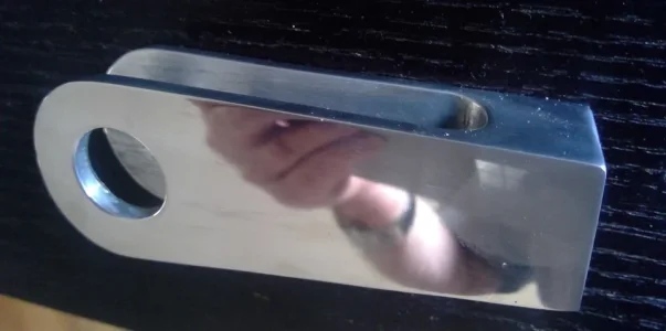
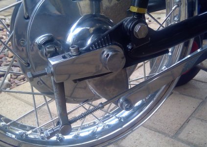
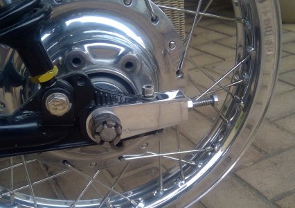
Next I machined one up from a solid lump of aluminium. I liked the look of this one, so made another matching one and fitted them both.
The adjusters on the TX were rusted, so I decided to made some new ones. My first thought was to make snail cams, as they provide a means of aligning the wheels without resorting to the use strings and straight edges. But they, being quite large, were just plain ugly, so they went in the bin.
Next I tried a fabricated one, bent around a 12 mm stainless nut I turned up, but, I just didn't ike the look of that one, so, it too went in the bin.
Next I machined one up from a solid lump of aluminium. I liked the look of this one, so made another matching one and fitted them both.
Attachments
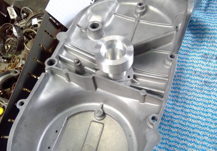
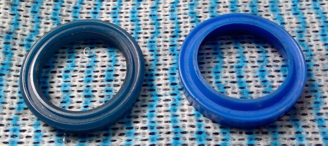
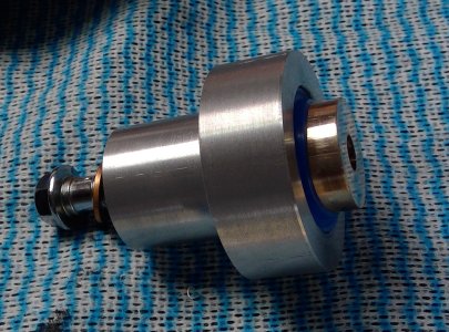
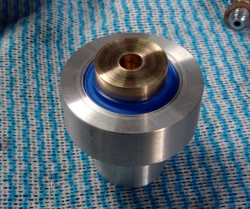
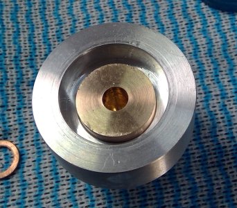
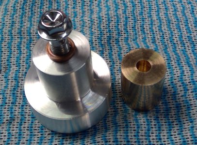
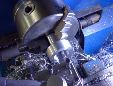
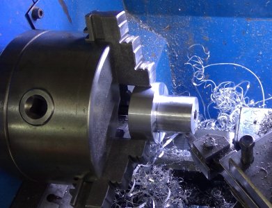
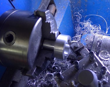
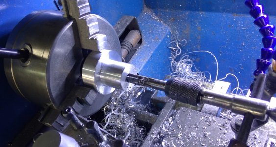
I made a hydraulic clutch slave cylinder to replace the cable, cable actuated is too heavy for my fused fingers. I bought some hydraulic ram seals and built the cylinder around them, body is 6061 and piston is bronze. Bore is dead on 25mm, piston i 24.7, a really nice fit. I still have to modify the left cover a little to fit it, but first I have to find a small master cyinder.
Attachments
-
 WIN_20230117_15_58_22_Pro.jpg511 KB · Views: 13
 -
 WIN_20230117_15_57_22_Pro.jpg394.7 KB · Views: 12
 -
 WIN_20230117_15_55_52_Pro.jpg290.8 KB · Views: 12
 -
 WIN_20230117_15_55_26_Pro.jpg331 KB · Views: 12
 -
 WIN_20230117_15_51_35_Pro.jpg266.9 KB · Views: 11
 -
 WIN_20230117_15_45_26_Pro.jpg362.6 KB · Views: 11
 -
 WIN_20230117_15_36_37_Pro.jpg473.2 KB · Views: 10
 -
 WIN_20230117_15_33_13_Pro.jpg452 KB · Views: 10
 -
 WIN_20230117_15_35_19_Pro.jpg535.7 KB · Views: 10
 -
 WIN_20230117_15_33_13_Pro.jpg452 KB · Views: 10
 -
 WIN_20230117_15_32_06_Pro.jpg367.9 KB · Views: 12
There’s a lot of trial in everything I build for this bike, I change my mind often, binning parts I made and buildIng new ones with a slightly different look or design changes to incorporate something else into the design.
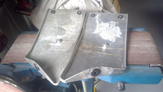
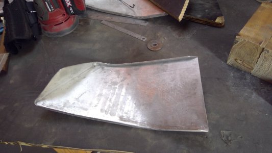
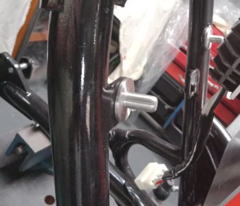
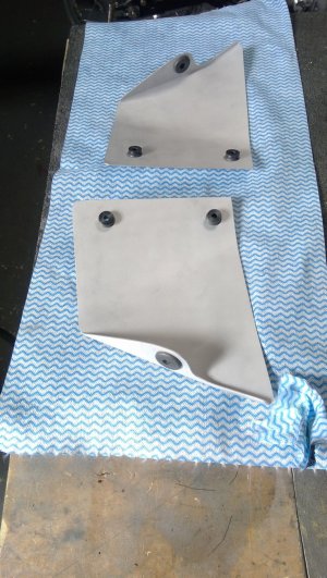
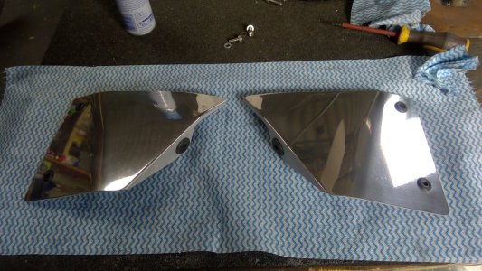
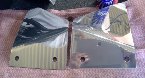
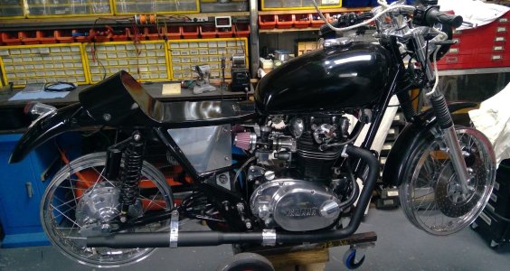
These side panels are a good example: Originally I built some full length ones because I hadn’t intended on running filters. They stretched from the rear frame tubes to the mid down tube. Because of the length I had to strengthen the 1.7mm aluminium I made them from so rolled the edge on three sides. The seat rails follow a completely different line from the straight lower frame rail, so as well as bending the panels to follow the line of the curved seat rail, I also had to twist the panels so they followed the line of the straight lower rail.
The panels have a grommet on the rear bend of the panel which slips over a bullet shaped knob I turned up and screwed to a small tab I welded to the rear down tube.. The front has two grommets into which two Allen heads are inserted and screw into plates I welded to the central frame down tube.
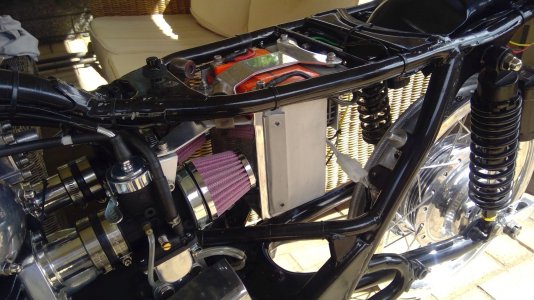
The panels were then polished and fitted, and then I changed my mind and decided to use either pod filters or stacks, the panels didn’t give enough room for their fitment, so, these panels went in the bin.
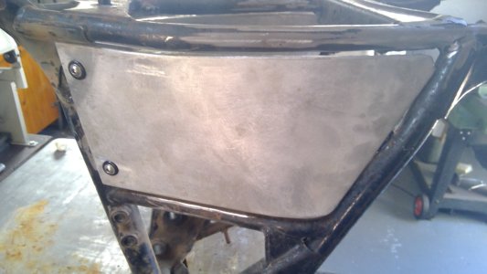
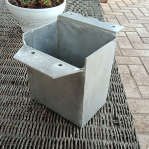
Next, I fabbed some shorter panels that ended at the front of the battery carrier, allowing plenty of room for pods or stacks. These panels being shorter didn’t require a rolled edge, just twisting and bending to follow the frame rails.
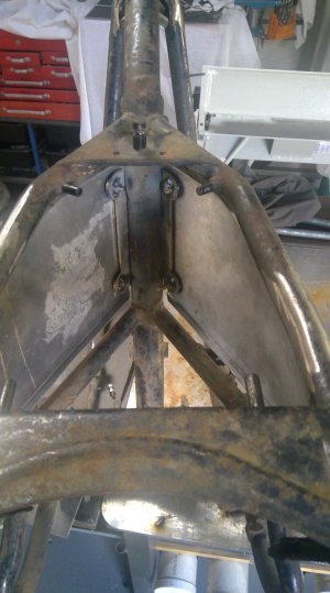
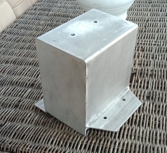
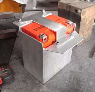
I utilised the rear mount, but the shorter panels required two mounting points at the front, the obvious mount point would be the battery carrier. So, I welded a couple of mounting strips on the side of the aluminium battery carrier, fitted two gromets at the front of the side panels and used stainless allen heads to screw them in place.
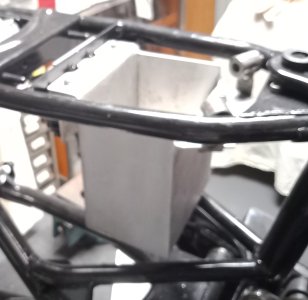
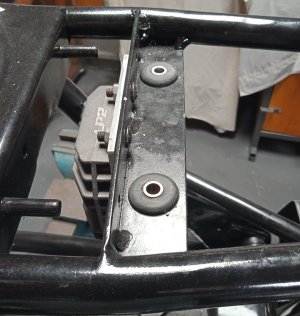
I welded a steel member across the frame to support the carrier and inserted grommets with Delrin T nuts so as to isolate the carrier from the fame. The original front frame mounts were utilised but I had to weld up a couple of steel brackets to mount the front of the carrier to. The panels are now triple mounted in rubber.
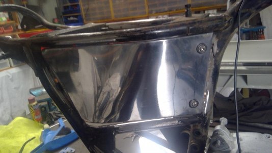
And then of course, I polished the side panels and the front of the carrier.
These side panels are a good example: Originally I built some full length ones because I hadn’t intended on running filters. They stretched from the rear frame tubes to the mid down tube. Because of the length I had to strengthen the 1.7mm aluminium I made them from so rolled the edge on three sides. The seat rails follow a completely different line from the straight lower frame rail, so as well as bending the panels to follow the line of the curved seat rail, I also had to twist the panels so they followed the line of the straight lower rail.
The panels have a grommet on the rear bend of the panel which slips over a bullet shaped knob I turned up and screwed to a small tab I welded to the rear down tube.. The front has two grommets into which two Allen heads are inserted and screw into plates I welded to the central frame down tube.
The panels were then polished and fitted, and then I changed my mind and decided to use either pod filters or stacks, the panels didn’t give enough room for their fitment, so, these panels went in the bin.
Next, I fabbed some shorter panels that ended at the front of the battery carrier, allowing plenty of room for pods or stacks. These panels being shorter didn’t require a rolled edge, just twisting and bending to follow the frame rails.
I utilised the rear mount, but the shorter panels required two mounting points at the front, the obvious mount point would be the battery carrier. So, I welded a couple of mounting strips on the side of the aluminium battery carrier, fitted two gromets at the front of the side panels and used stainless allen heads to screw them in place.
I welded a steel member across the frame to support the carrier and inserted grommets with Delrin T nuts so as to isolate the carrier from the fame. The original front frame mounts were utilised but I had to weld up a couple of steel brackets to mount the front of the carrier to. The panels are now triple mounted in rubber.
And then of course, I polished the side panels and the front of the carrier.
Attachments
-
 311868149_3393100767616612_7731257055446653241_n.jpg295.6 KB · Views: 12
 -
 312428619_3393100807616608_965464294712658013_n.jpg253.1 KB · Views: 12
 -
 311729359_3393100877616601_771371738814419082_n.jpg217.2 KB · Views: 11
 -
 312187215_3393100917616597_4786894310735577472_n.jpg246.2 KB · Views: 11
 -
 311668641_3393100964283259_2392233840788869179_n.jpg210.3 KB · Views: 12
 -
 311694714_3393101007616588_3308746523272833043_n.jpg135.6 KB · Views: 11
 -
 311850024_3393101120949910_1242515116984288932_n.jpg438.8 KB · Views: 13
 -
 311770201_3393101177616571_2074751161806245333_n.jpg438 KB · Views: 13
 -
 312298306_3393102350949787_7119916080805265771_n.jpg314.6 KB · Views: 10
 -
 312180353_3393102467616442_4451544592267648841_n.jpg559.4 KB · Views: 12
 -
 311830558_3393102537616435_3669038976904043244_n.jpg643.2 KB · Views: 11
 -
 312107372_3393102584283097_5289488312883518342_n.jpg445.5 KB · Views: 11
 -
 312199032_3393102620949760_1763313378110830435_n.jpg214.2 KB · Views: 13
 -
 311914996_3393102664283089_8293746607337106377_n.jpg108.4 KB · Views: 10
 -
 312289780_3393102714283084_1501744946273500034_n.jpg314.6 KB · Views: 13
 -
 311834981_3393105914282764_5820243012265259453_n.jpg373.9 KB · Views: 12
 -
 311730023_3393105964282759_6515560355297643640_n.jpg309.2 KB · Views: 12
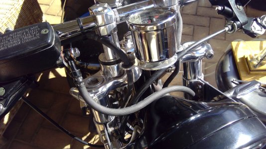
A brake hose dividing block.
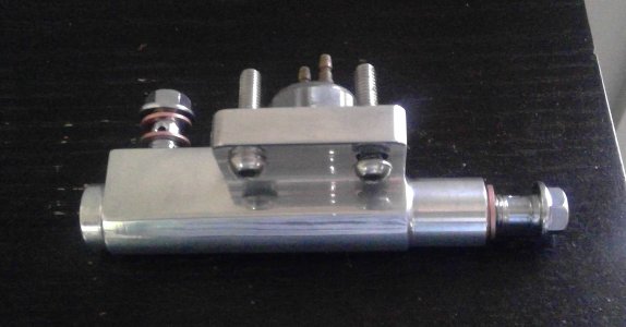
This is a new brake line block I machined up to replace the original. The original hoses were rotted, so I replaced them and did away with the two steel tubes that connect the hose to the calliper and the hose from the master cylinder to the divider. Unfortunately, the new hoses have the banjos on the same plain requiring the lower hose to be twisted through 90degrees to connect to the original divider, so I machined a new divider to get around the problem. The lower hose connects at the rear of the divider, as does the brake light switch. The top hose connects to the side of the divider.
This is a new brake line block I machined up to replace the original. The original hoses were rotted, so I replaced them and did away with the two steel tubes that connect the hose to the calliper and the hose from the master cylinder to the divider. Unfortunately, the new hoses have the banjos on the same plain requiring the lower hose to be twisted through 90degrees to connect to the original divider, so I machined a new divider to get around the problem. The lower hose connects at the rear of the divider, as does the brake light switch. The top hose connects to the side of the divider.
Attachments
-
 310290408_3390827947843894_3792670857924279849_n.jpg232.3 KB · Views: 10
 -
 307678224_3390828151177207_4124538913492109092_n.jpg309.3 KB · Views: 12
 -
 310310999_3390828724510483_4939313714668790861_n.jpg390.1 KB · Views: 11
 -
 310485007_3390828084510547_1536601018598377535_n.jpg415.7 KB · Views: 10
 -
 310502716_3390828187843870_7282701913890634183_n.jpg174.3 KB · Views: 10