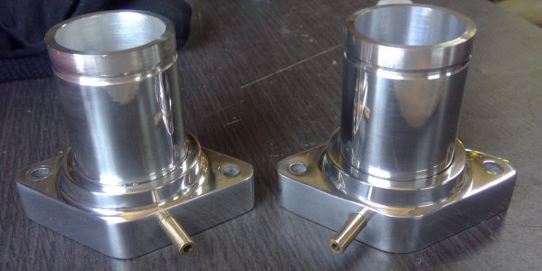
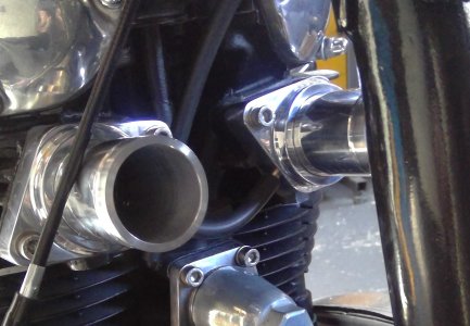
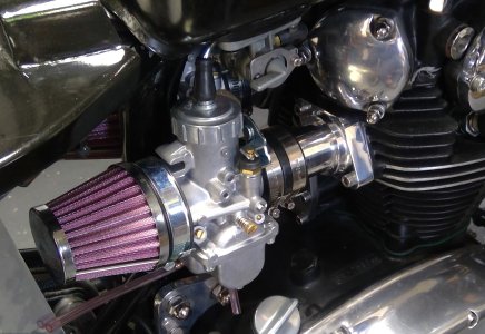
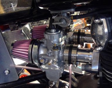
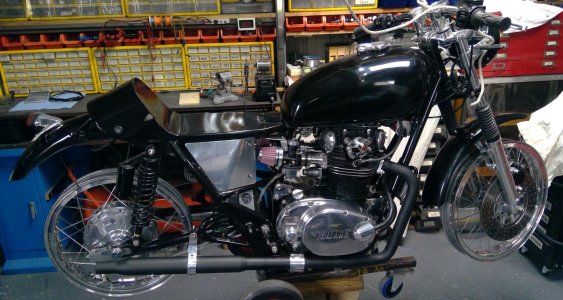
I've done many, many mods to this bike, not much is standard: cooler, spin on filter, single points, permanent magnet alternator, cutch slave cyinder, manifolds, VM carbs, pcake filters, handbeaten side panels, tai ight, battery carrier, hdlight brackets, fue distributer, brake joining block, wiring harss x2, engine brackets, cable splitter, etc,etc, etc. All hand built in my workshop.
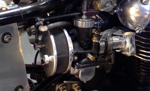
This is the cooler/spin on filter conversion I did.
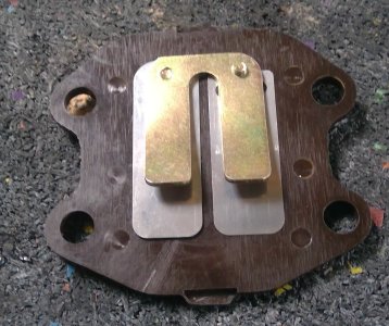
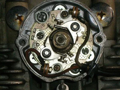
The XS650 has two oil filters, well, strainers really, one in the sump and one in the right side cover. As said, they are strainers rather than filters and as such not particularly good at filtering the oil. The system works thus: There is an oil pump in the right side cover, it draws oil from the sump via a sump strainer, The pump pumps oil up a 10mm hole toward the front of the side cover, the 10mm hole is stoppered at the front of the cover via a 10mm bung. The 10mm hole from the pump is cross drilled from the right side strainer void, so, the oil is pumped through the 10mm hole then off at a right angle via the cross drilling through a strainer contained within the right side cover then on to the engine.
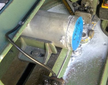
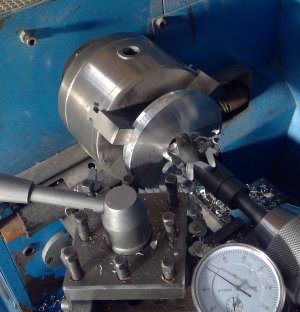
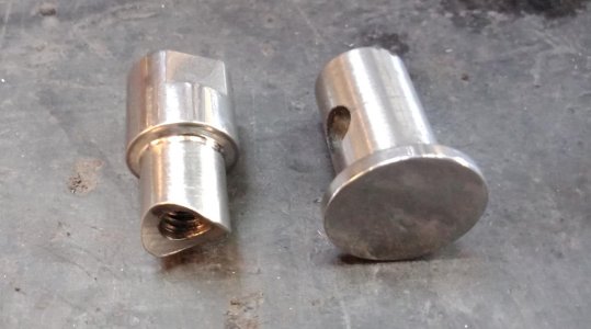
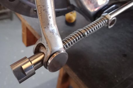
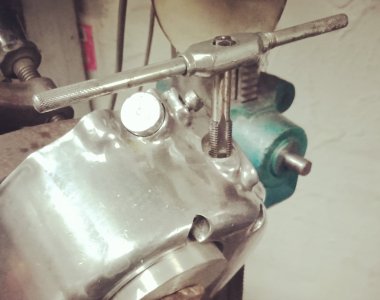
So to fit a remote spin on filter I removed the bung at the front of the side cover, mounted the side cover on the drill press table and angled it so the 10mm hole from the oil pump was vertical. The hole is set at an odd angle on two axis' to the cover, so setting the 10mm hole vertical was a job in itself. Once setup correctly, I drilled the 10mm hole out to 10.8mm then tapped it to M12 x 1.25 for 40mm so passing the cross drilling to the side cover strainer, I then countersunk the top of the hole to allow for an O ring and inserted a stainless spigot I turned up and threaded. This spigot covers the cross drilling leading to the side cover strainer.
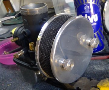
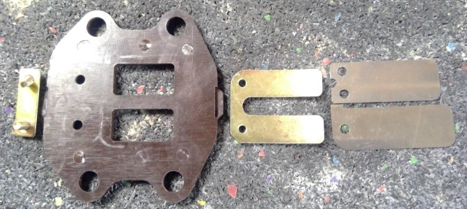
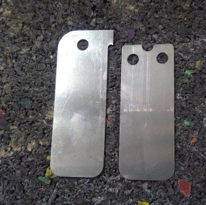
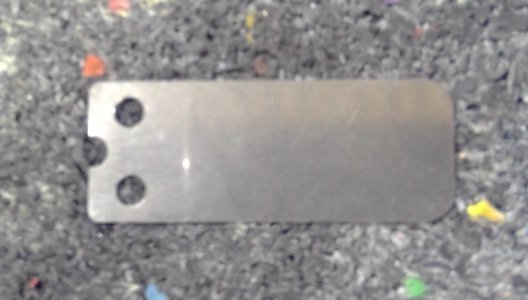
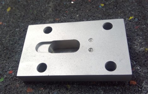
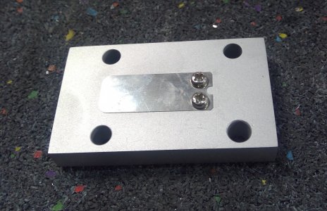
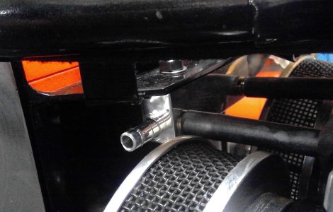
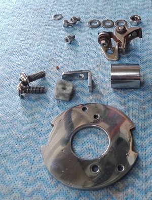
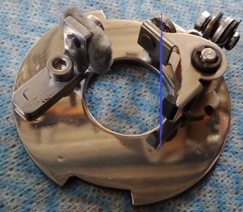
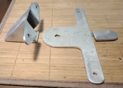
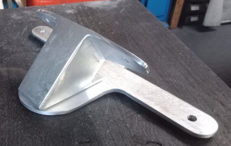
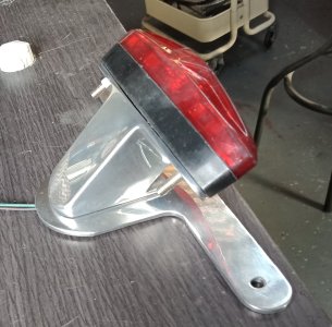
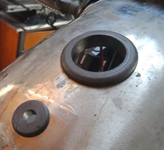
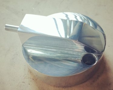
Next I binned the side cover strainer cover and machined up a new one, which I think looks a lot better than just screwing a right angle, screw in fitting on the original part. Took a bit of doing this part as the outer side had to be angled to follow the angle of the side cover. Rather than use an ugly screw in fittings, I spun up a stainless barb and shrunk it in place.
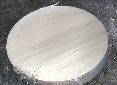
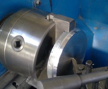
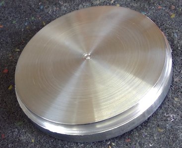
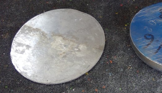
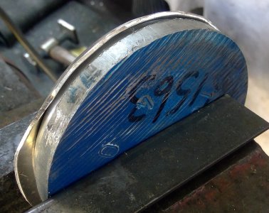
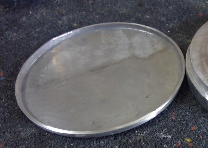
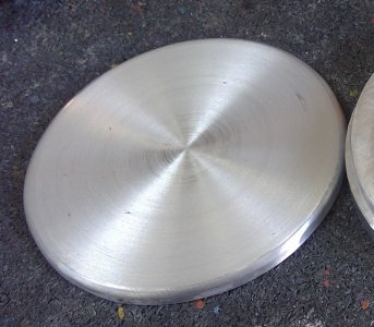
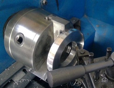
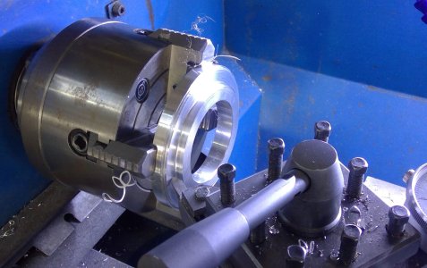
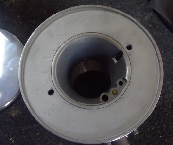
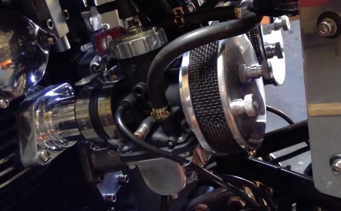
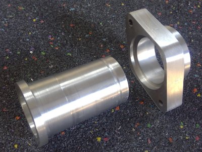
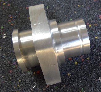
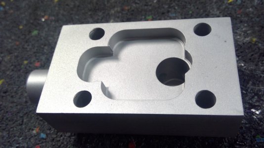
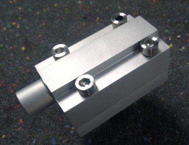
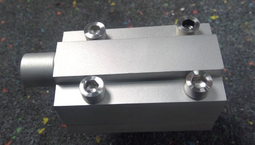
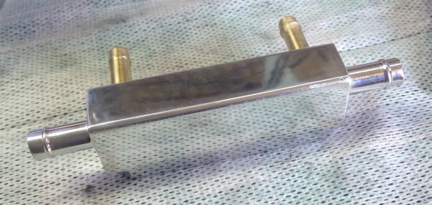
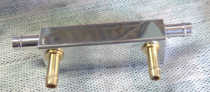
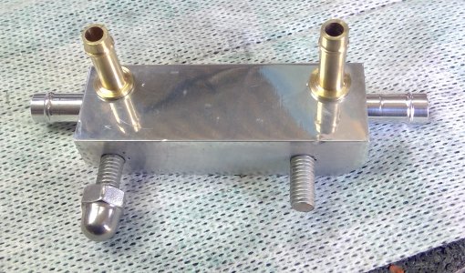
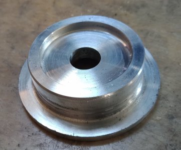
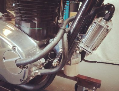
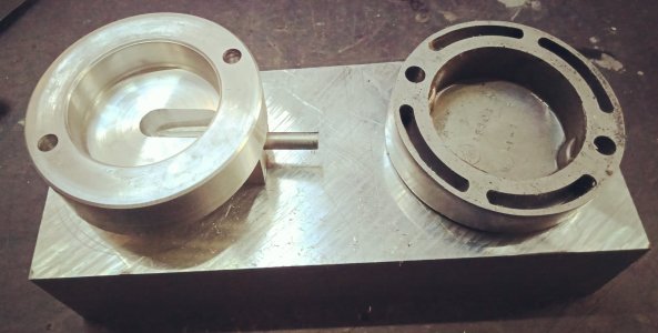
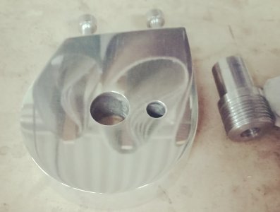
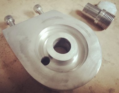
Next came the spin on filter mount. I made this from a lump of 25mm ally, machined it to the desired shape, drilled and tapped the side for mounting screws, then mounted it in the lathe to machine the oil gallery recess, once done I drilled a central hole for oil output and a second hole through to the recess for the input. I then spun up a threaded piece on which to spin the filter and pressed it into the housing, turned up a stainless, threaded barb, screwed it into the spin on filter threaded piece, sandwiching the filter mount between. There was insufficient space for a screw in input barb, so I spun up a barb for an interference fit and pressed it into place.
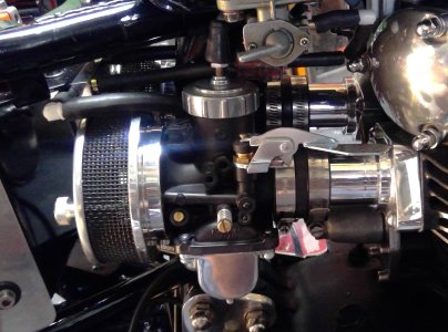
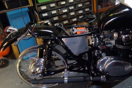
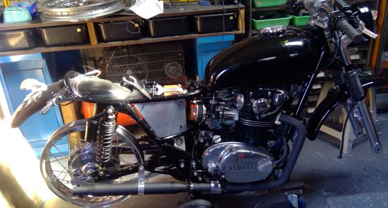
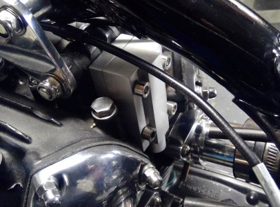
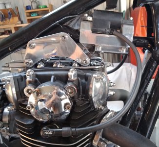
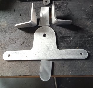
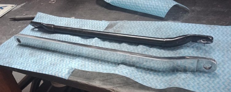
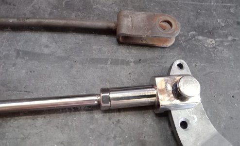
I then fabricated some new engine mounts on which to mount the filter mount and oil cooler. The engine mounts were basically the same as the original ones I made, the right has been extended downward around 25mm for the filter mount and both drilled and tapped at the front edge for mounting a cooler bracket.
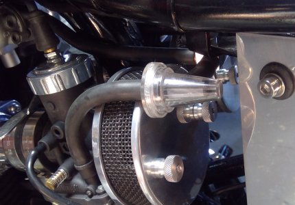
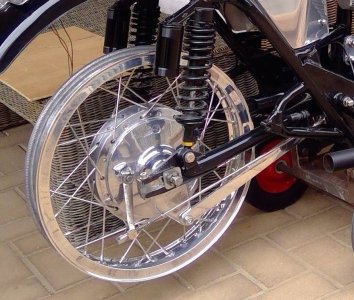
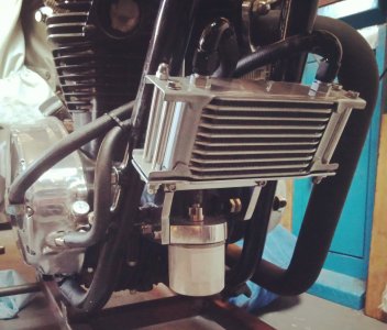
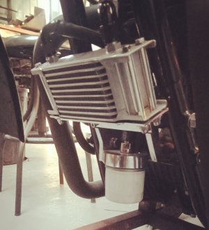
The cooler bracket is just a piece of 3mm ally bent at a right angle so the cooler mounts on top. I had to cut some 10mm ally tube to fit between the cooler mounting fins and recess the mounting bracket holes a little so I could install some rubber grommets to insulate the cooler from vibration. To hold it in place I cut some 6mm bolts to size and spun up some threaded positive stop, ally T nuts.
Last of all, I polished everything.
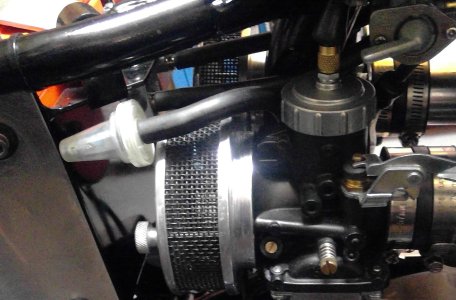
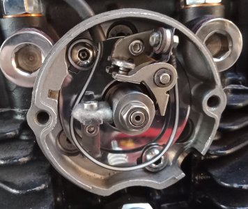
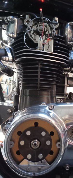
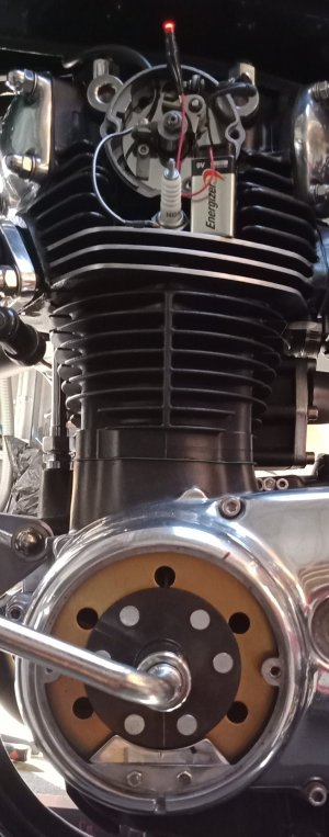
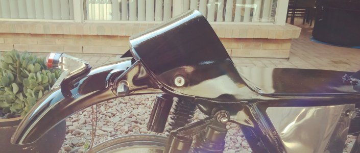
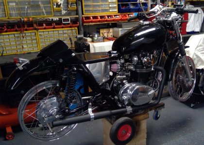
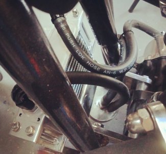
So, the system now works thus: The pump picks up oil from the sump via the sump strainer, pumps oil up the 10mm hole exiting the side cover at the front via the stainless barb. It then travels through a hose to the spin on filter then on to the cooler and then back to the side cover strainer cover via another hose, then into the void where the strainer once sat, then on to the engine.
It was quite a bit of work, but I enjoy working in my workshop, so, nothing is too much work for me.
This is the cooler/spin on filter conversion I did.
The XS650 has two oil filters, well, strainers really, one in the sump and one in the right side cover. As said, they are strainers rather than filters and as such not particularly good at filtering the oil. The system works thus: There is an oil pump in the right side cover, it draws oil from the sump via a sump strainer, The pump pumps oil up a 10mm hole toward the front of the side cover, the 10mm hole is stoppered at the front of the cover via a 10mm bung. The 10mm hole from the pump is cross drilled from the right side strainer void, so, the oil is pumped through the 10mm hole then off at a right angle via the cross drilling through a strainer contained within the right side cover then on to the engine.
So to fit a remote spin on filter I removed the bung at the front of the side cover, mounted the side cover on the drill press table and angled it so the 10mm hole from the oil pump was vertical. The hole is set at an odd angle on two axis' to the cover, so setting the 10mm hole vertical was a job in itself. Once setup correctly, I drilled the 10mm hole out to 10.8mm then tapped it to M12 x 1.25 for 40mm so passing the cross drilling to the side cover strainer, I then countersunk the top of the hole to allow for an O ring and inserted a stainless spigot I turned up and threaded. This spigot covers the cross drilling leading to the side cover strainer.
Next I binned the side cover strainer cover and machined up a new one, which I think looks a lot better than just screwing a right angle, screw in fitting on the original part. Took a bit of doing this part as the outer side had to be angled to follow the angle of the side cover. Rather than use an ugly screw in fittings, I spun up a stainless barb and shrunk it in place.
Next came the spin on filter mount. I made this from a lump of 25mm ally, machined it to the desired shape, drilled and tapped the side for mounting screws, then mounted it in the lathe to machine the oil gallery recess, once done I drilled a central hole for oil output and a second hole through to the recess for the input. I then spun up a threaded piece on which to spin the filter and pressed it into the housing, turned up a stainless, threaded barb, screwed it into the spin on filter threaded piece, sandwiching the filter mount between. There was insufficient space for a screw in input barb, so I spun up a barb for an interference fit and pressed it into place.
I then fabricated some new engine mounts on which to mount the filter mount and oil cooler. The engine mounts were basically the same as the original ones I made, the right has been extended downward around 25mm for the filter mount and both drilled and tapped at the front edge for mounting a cooler bracket.
The cooler bracket is just a piece of 3mm ally bent at a right angle so the cooler mounts on top. I had to cut some 10mm ally tube to fit between the cooler mounting fins and recess the mounting bracket holes a little so I could install some rubber grommets to insulate the cooler from vibration. To hold it in place I cut some 6mm bolts to size and spun up some threaded positive stop, ally T nuts.
Last of all, I polished everything.
So, the system now works thus: The pump picks up oil from the sump via the sump strainer, pumps oil up the 10mm hole exiting the side cover at the front via the stainless barb. It then travels through a hose to the spin on filter then on to the cooler and then back to the side cover strainer cover via another hose, then into the void where the strainer once sat, then on to the engine.
It was quite a bit of work, but I enjoy working in my workshop, so, nothing is too much work for me.
Attachments
-
 tapping the side cover.jpg160.9 KB · Views: 14
 -
 remote filter cooler fitted right.jpg243.5 KB · Views: 19
 -
 remote filter cooler fitted right 2.jpg204 KB · Views: 12
 -
 remote filter cooler fitted left.jpg230.9 KB · Views: 10
 -
 remote filter coller complete top.jpg246.5 KB · Views: 11
 -
 engine mounts oil filter housing complete.jpg170.3 KB · Views: 10
 -
 oil inlet cover outer.jpg215 KB · Views: 12
 -
 oil inlet cover inside comparo.jpg152.3 KB · Views: 12
 -
 oil filter housing outer.jpg107.8 KB · Views: 11
 -
 oil filter housing inner.jpg137.6 KB · Views: 11
 -
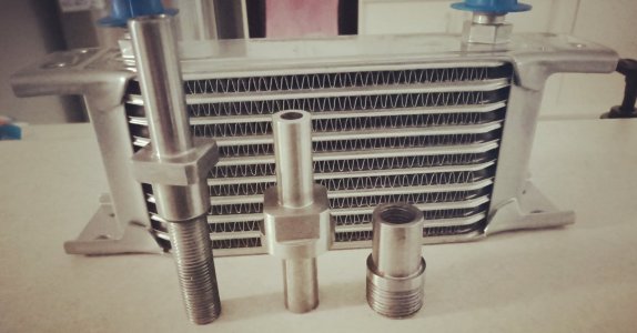 oil cooler and barbs.jpg127.5 KB · Views: 14