• Spring 2024 meetup in Calgary - tentative date Saturday, April 20/2024. Other regions are also discussing meet ups. If you want one in your area get going on organizing it! discussion
  • We are having email/registration problems again. Diagnosis is underway. New users sorry if you are having trouble getting registered. We are exploring different options to get registered. Contact the forum via another member or on facebook if you're stuck. Update -> we think it is fixed. Let us know if not.
  • Spring meet up in Ontario, April 6/2024. NEW LOCATION See Post #31 Discussion NEW LOCATION

AMMEND Needing help with WIRING some steppers to arduino.

I guess I should be a little clearer.

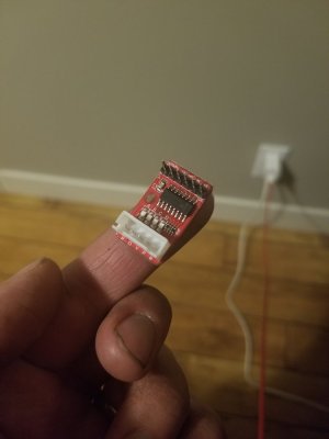
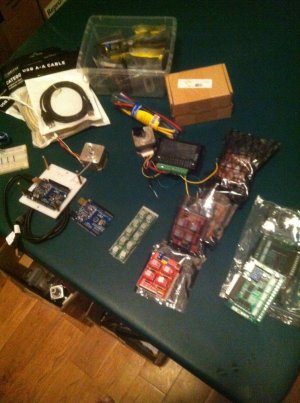
I'm looking for someone to help me wire a small stepper to an Arduino board. What ever I try it doesn't seem to work. not sure if I've blown something, wrong software. Is anybody running an Arduino that I can come over to see what your looks like.

Please text if you can help, I'm home 95% of the time.

Thanks Brian
403-852-3087
bj.lawrence@shaw.ca
 

Janger

(John)
Administrator
Vendor
Do you have a stepper motor controller too? I don’t think the arduino will drive a stepper directly. I am using a grbl board which has motor controllers and interprets gcode...
 

kylemp

Well-Known Member
I think it's POSSIBLE to drive a tiny stepper with an arduino.. but you wouldn't want to do that. Do you have a stepper driver? If you do you'd only need to send step signals to make sure it's working.. pull the direction high and step again, and you'll reverse.
 

Alexander

Ultra Member
Administrator
Kyle I don't believe you can drive a stepper with an arduino uno. But there are some arduino boards with an integrated stepper motor driver. This is a tiny stepper motor driver that you need in between your arduino uno and the stepper motor. Keep in mind this is too small do be useful for machining.
 

Attachments

  • 1513230006862786560684.jpg
    1513230006862786560684.jpg
    51.7 KB · Views: 9

Alexander

Ultra Member
Administrator
I should go on to say I am interested in learning about the same thing that Brian is asking about but I have no experience in these things.
 
Hopefully I have several of everything, and different kinds as well (Old and New). that's probably a lot of my problems. I'm not sure what goes with what or is it software that's lacking.
The motors are no bigger that a roll of Scotch Tape.
 

Attachments

  • IMG_0993.JPG
    IMG_0993.JPG
    164.7 KB · Views: 10

Janger

(John)
Administrator
Vendor
I have one of these https://www.synthetos.com/project/grblshield/
which goes on top of the arduino board and has four pins for each stepper xyz. It was pretty easy to get going and will drive the motors with gcode downloaded to the arduino.

I’ve done some basic breadboard wiring and the motors spin but that’s as far as I’ve gone. It’s very interesting though and I’d like to know more and how to do more with it. Time... need more time. Work really gets in the way :p

What equipment are other people using?

Brian do you have something like this in your pile of stuff?

Edit -> adding photo
 

Attachments

  • 69EA8D4A-B9CA-4C94-BCD8-97C805E66463.jpeg
    69EA8D4A-B9CA-4C94-BCD8-97C805E66463.jpeg
    98.4 KB · Views: 9
Last edited:

Johnwa

Ultra Member
Hopefully I have several of everything, and different kinds as well (Old and New). that's probably a lot of my problems. I'm not sure what goes with what or is it software that's lacking.
The motors are no bigger that a roll of Scotch Tape.
The red pcb that’s still in its plastic wrapper looks like a stepper driver shield that’s good for <2 amps. It plugs into the top of a UNO. It also needs a separate power supply to drive the steppers. Then it’s just a matter of wiring it up and getting whatever software you’re using to work.
I didn’t look but there should be some simple stepper sketches on the web. In any case, there are only 3 signals from the UNO to the shield that matter. Enable, Direction, and Step. The EN is held either high or low, I don’t recall which to enable the driver. For testing Dir can be either high or low. Step is just a series of pulses that drives the stepper. One pulse every millisecond should work
 

Johnwa

Ultra Member
Here’s a picture of a shield with two steppers connected. In the top right I have a 12v supply connected. The shield will handle up to 36v. If the EN is pulled low the driver is energized and the stepper will be hard to turn by hand. According to this schematic https://blog.protoneer.co.nz/wp-content/uploads/2013/07/Arduino-CNC-Shield-Scematics-V3.XX_.jpg EN corresponds to pin 8 on the Arduino. You can write a simple sketch to pull EN low, that will confirm whether or not the driver is working.
A1925CB2-3AD2-4CDA-851A-EEF97603D5E5.jpeg .
 

Janger

(John)
Administrator
Vendor
I have in my Cnc mill some pretty Big steppers each one has its own driver board with a common but separate power supply. The motors are probably 4”x4” by 5 or 6”. How many amps or better how many watts would a motor like that need? How many amps could that board you show drive @Johnwa ?

If you wanted to drive bigger steppers from an arduino what shield would you buy? The grbl shield says nema17 or nema23 max.
 

Johnwa

Ultra Member
With a heat sink the shield I used is rated up to 2 amps. I think that’s optimistic. In my picture just above the heat sink there is a little trim pot that allows you to adjust the maximum current. I turn it down until the stepper starts to stall. Even then these drivers run fairly hot, like burn your finger hot!

I’ve never found a shield that was rated more than about 2 to 3 amps. I’ve got a few of these https://www.aliexpress.com/item/TB6...32629936087.html?spm=a2g0s.9042311.0.0.RuXZVg They’re good for 4 amps. They take 5 V signals so can be connected to an Arduino.

Your steppers should have a label that gives its maximum amps. Your driver should supply that. The higher voltage the driver is the quicker it can raise the current from 0 to max so it will have higher torque.
 

Alexander

Ultra Member
Administrator
@Janger your steppers are just over 2 amps each. The voltage is on the power suply I think they are 24v dc but i can not remember.
 

Alexander

Ultra Member
Administrator
The only think I know for sure is the motors on the machine John has are nema 34 and about 800oz/in so too big for any tiny arduino shield gadget.
 
Sorry for the delay. here's more pictures of what was in the first pictures.
IMG_1002[1].JPG IMG_0995.JPG the older style driver (I think this driver can go up to 5A )and board with lpt1 port (RS232).
IMG_0996.JPG IMG_0999.JPG IMG_1001.JPG IMG_1003.JPG
These next 4 pics are another system. the Uno board, Controller board, & driver chips, All three put together, and finally a top view of all three put together.
The motors are a whopping 0.9A.
I have wired them like Johns' picture, but Nothing. Did I blow something playing with it? Can they be tested?
That's why I bought 5 of them, cause I knew this was going to happen to me.
My next step I think is to mock up the way I have it wired, then take a picture of it, and let you guy's decide.
Info: Using an XP computer which I installed a lpt1 port (and it's drivers)just to make sure incase I use the picture 1 board with the RS232 connection.
I've got Mach3 installed, Grbl Controller installed, EFL CNC installed which may or may not be configured right?? Are they conflicting with each other???
Ok Next report will be what I think is the wiring, and answer any question any one might have.

I appreciate all the help

Brian
 

Johnwa

Ultra Member
The only think I know for sure is the motors on the machine John has are nema 34 and about 800oz/in so too big for any tiny arduino shield gadget.

If the motors are only drawing 2 amps the shield in my picture might work in a pinch. The driver that plugs into my shield is only $1 a piece, so smoking one is no biggie. The one Janger linked to with a 2.5amp rating would allow for a bit of headroom but it would hurt to smoke that one.
 
Ok here's goes....
Picture 1 IMG_1005[1].JPG on the top left I've connected the communication cable.
Bottom left is the power (12V Max 5A)

Picture 2
IMG_1006[1].JPG Next board on top of the first board.
About top Middle you'll see the motor connection to the X axis.
Lower left is the power which is 24V supply Max 6A.

What am I missing so far???

Does it look right???

Brian
 

Johnwa

Ultra Member
Everything looks ok to me.
Try setting the trim pot midrange in case it is currently at zero. You can also check for continuity of the stepper windings. One winding will be the red wire and the wire next to it.

You don’t need to power the uno through its power jack, the USB cable will provide enough power for the 5v side. But either way it shouldn’t interfere with anything.
 
Top