• Scam Alert. Members are reminded to NOT send money to buy anything. Don't buy things remote and have it shipped - go get it yourself, pay in person, and take your equipment with you. Scammers have burned people on this forum. Urgency, secrecy, excuses, selling for friend, newish members, FUD, are RED FLAGS. A video conference call is not adequate assurance. Face to face interactions are required. Please report suspicions to the forum admins. Stay Safe - anyone can get scammed.

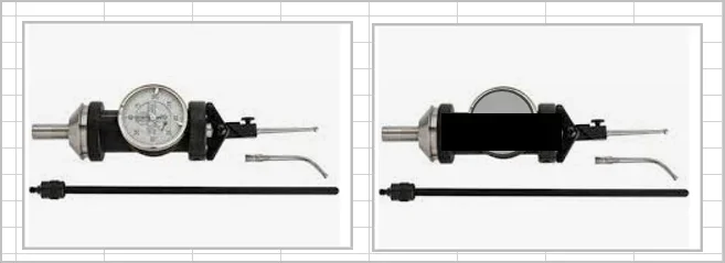
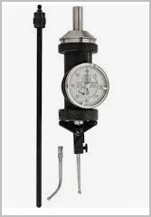
Aliexpress Coaxial Indicator

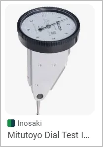
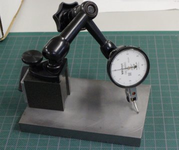
Here is a DTI (dial test indicator) for you @PeterT . They don't have great accessibility.
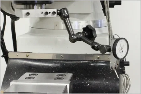
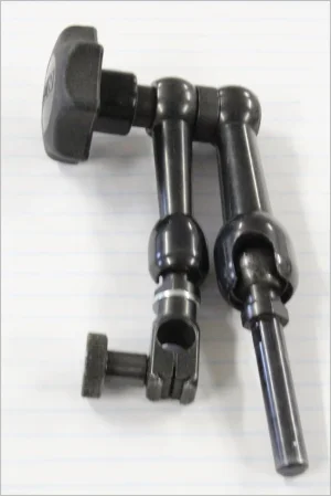
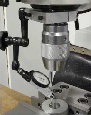
What you need is a Noga arm. The one I have has a plain shank end which goes into the drill chuck or collet or whatever. Or as shown, adapted to a quill clamp so you don't have to disturb any mounted parts or in-situ tooling to do indicating. This clamp was a prototype to allow the shank to be placed vertically or horizontally, but I want to make one more like the open C shape with a single tightener. Anyways, it takes about 3 seconds to have the DTI ball on a surface ready to rotate. I would argue the DTI can go places the Blake cannot because the Blake indicator arms are bent a certain way & limited in span. This is the short Noga, my vise is 5" for reference.

1703908201179.png
1703908233687.png
1703908167370.png
 
I bought mine for re-boring pulleys. I was rebuilding several machines, and I had to bore out some pulleys. These were used pulleys, and the bore wasn't very pretty. I could reach all the way to the bottom of the pulley to find good parts of the bore.

It is also a lot faster to use, if you get the hang of it. You aren't craning your neck or using a mirror to see the dial when it is facing away from the operator.

One other way it shines is when you are indicating on the outside of a large circular object. It can be done with a DTI and a flexible arm, but there is quite a range the coax is faster and more convenient. But only once or twice a year (for me, anyway)

- This sounds like I'm a big fan. I'm not, really. The few times it is needed it is a blessing. Otherwise I reach for my Mit DTI (I'm not an animal!) :eek: - I got mine for 75$ and for that price it is well worth it.
 
Last edited:
What you need is a Noga arm.

Too funny @PeterT. I don't need anything. You wanted a photo of a DTI. I assumed you wanted to clarify what @Dabbler was talking about. You said you would post a photo and then didn't. So I figured you just forgot.

I think you just know that lots of folks on here confuse DTIs with DIs (plunge indicators). So I helped you out with a photo. Nothing more, nothing less. LOL!
 
This sounds like I'm a big fan. I'm not, really. The few times it is needed it is a blessing. Otherwise I reach for my Mit DTI (I'm not an animal!) :eek: - I got mine for 75$ and for that price it is well worth it.

I am the same. I have all sorts of indicators. My CoAx indicator mostly gathers dust. My favorite is a mitutoyo DTI AND I AM AN ANIMAL!

One of the features of the Co-ax indicator that nobody has mentioned is that they will indicate in both plus and minus directions from a zero point. So will most DTIs, but you have to flip a lever to do it while the co-ax will just do it all the time. I've never used this feature but I did note that it's there.

The other thing about them is the way they are designed to be chucked in a spindle. You can chuck a regular DTI too, but good luck reading it while the chuck turns. The coax indicator body stays in one place while it's axis spins co-axially (hence its name) with the spindle. In this way it's sort of like the difference between a mill and a lathe - in one case the work spins and in the other the tools spin. This has its uses too.

My advice to most is that a co-ax indicator is not an essential piece of instrumentation. I'd only buy one if I got a really good deal cuz it will mostly gather dust.
 
It's probably one of those things where both devices have their pros & cons & overlap. The best solution is for us to have both available in the cabinet! More tools! Bwa-ha-ha-haaa

You can chuck a regular DTI too, but good luck reading it while the chuck turns.
No its not spinning obviously, mill is in neutral drive & you are controlling the measurement position with your hand. You position it & read the dial, takes longer to type than to do it
BTW there are top facing dials, I have one, I just keep forgetting to use it because I'm used to my regular one.
1703958627014.png


Actually thing brings up another point about the dial facing away &/or requirement for a mirror etc. I rarely if ever use a mirror for most part. I focus on Left, Right & Facing me (3 quadrants) until the needle is same position. I do shift myself a bit to see Left or Right facing but I also find it easier to make precise handwheel adjustments to converge needle position anyway. Rarely does it take more than 3 divide-the-difference iterations & needle should be entirely static. Which, if you had a tenths DTI, means you are accurate to tenth (COAX are 0.001"). What WILL drive you nuts with a DTI is if you are off center by a large amount & needle is swinging wildly. Don't do that. I'm lucky & have a DRO so I can use practically anything including the DTI ball itself & DRO half function so the whole exercise is converging the last 0.002" or so.

Anyways, if the measurement feature (typically a ID hole or OD boss) is truly circular, the 4th rear facing will indicate same as front facing once the 3 quadrants are dialed. But always wise to do a sanity check. If feature is not truly circular, that's a different issue & neither instrument will tell you center, or at least without a bit more elaboration of the non-circular feature. Think of simple deviation like an elliptical hole. The COAX will settle to some kind of minimal spread needle blur vs DTI will say something like +0.001 left, -0.001 right, 0.000 center face (0.000 rear face). Tomatoes, tomahtoes. If the ellipse axis is angled, its kind of the same but the measurements don't represent quadrants anymore.

I like that the machine is not running and I am free to sweep & examine any position of the circumference. Example if the hole has a negative nick or positive burr on the wall, DTI can clearly see that with a hand held sweep & work around / re-adjust measurement positions accordingly. But COAX will always blindly run over that obstruction & its needle registers it as a deviation indistinguishable from a centering issue. If I recall my COAX also had an arm sticking out the side which had to be be static. So that either requires hand holding or mag base stop post or whatever. Now as I type this, maybe that is a 'feature' in that rotating the handle to examine needle blur in another axis (elliptical hole example).
 
Last edited:
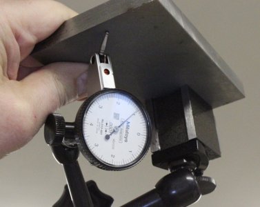
Hmm, I wonder. Would the COAX also be subject to gravity DTI / holder upside-down-itis as the arm rotates? The COAX needles are typically much heavier stock & the mechanisms are not exactly Swiss watch. I really don't know the answer. Field test with independent measurement required, I vote you haha. (This is my Noga mini mag base test but I've seen the same test with a very solid locked down holder & seem to recall the discussion was on DTI's with holder eliminated).
 

Attachments

  • IMG_1817_edited-1.jpg
    IMG_1817_edited-1.jpg
    33.1 KB · Views: 4
  • IMG_1815_edited-1.jpg
    IMG_1815_edited-1.jpg
    46.1 KB · Views: 4
No its not spinning obviously, mill is in neutral drive & you are controlling the measurement position with your hand.

Yes, it actually can be spinning! I know cuz I've done it! Albeit at low speed but it certainly works just fine at low speeds. It's something to see! Someplace I remember reading not to exceed 750 rpm. There is a handle that you hold (or block) to stop the indicator from spinning while the spindle spins.

Would the COAX also be subject to gravity DTI / holder upside-down-itis as the arm rotates?

I believe it has to. But it's prolly insignificant until the unsupported mass gets too great or the system ridgitity gets too low.

In as much as most indicators are not absolute and these things certainly are not, I don't think it matters unless you are switching back and forth.

I vote you haha.

And I vote YOU! LOL!

NOW WHAT?

Arm wrestle?

I already flipped a coin and you lost......
 
I sold my COAX long time ago, so alas, I cannot be a tailstock test pilot contender. But I will break out my top reading DTI for a photo op.

But it would be interesting for someone to do the inverted (gravity) test like my post #28 pictures with a COAX. I'm struggling to remember if the drift issue was with the arm or the DTI or a bit of each.
 
have a DRO so I can use practically anything including the DTI ball itself & DRO half function
There's a piece of magic to apply - I wish I'd thought of that as the way to get to the first "close enough" reading! Thanks!
 
I sold my COAX long time ago, so alas, I cannot be a tailstock test pilot contender. But I will break out my top reading DTI for a photo op.

But it would be interesting for someone to do the inverted (gravity) test like my post #28 pictures with a COAX. I'm struggling to remember if the drift issue was with the arm or the DTI or a bit of each.

OK, you win. I'll do it.

It's easy to see what you are doing with the DTI. Again, I don't think it matters unless you are comparing the two readings in the two cases - which I wouldn't do. But it's not obvious to me what you want to evaluate with the Coax. Can you describe the test you want to do in more detail?
 
Hmm, I wonder. Would the COAX also be subject to gravity DTI / holder upside-down-itis as the arm rotates? The COAX needles are typically much heavier stock & the mechanisms are not exactly Swiss watch. I really don't know the answer. Field test with independent measurement required
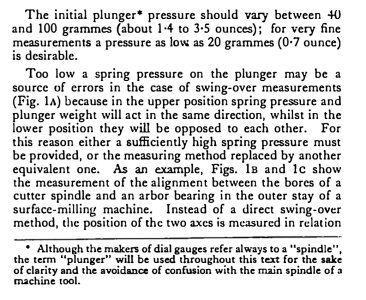
Here is an excerpt from Schlesinger's book, "Testing Machine Tools" (which we have a copy on this sites reference library).
 

Attachments

  • Screenshot_20231231_070450_Adobe Acrobat.jpg
    Screenshot_20231231_070450_Adobe Acrobat.jpg
    197.2 KB · Views: 7
But it's not obvious to me what you want to evaluate with the Coax. Can you describe the test you want to do in more detail?

Just the 'inverted test' with an indicator arm screwed in. (Left) chuck the coax on its stem in the lathe, zero the dial. Then (right) rotate chuck 180-deg & record any needle movement, likely require a mirror.

1704037808030.webp
 

Attachments

  • 1704037792314.webp
    1704037792314.webp
    3.1 KB · Views: 1
No its not spinning obviously, mill is in neutral drive & you are controlling the measurement position with your hand.

My memory isn't that bad on this one. I surprised myself! I had said 750. The Blake website for their coax indicator says max rpm is 700 - 800 rpm. I think much less than that is better but for some machines I suppose that may not be possible. The relevant part starts just before 3 min in their video where they show how to use it with the spindle turning. In fact they imply that this is the way it is supposed to be used.


A question for anyone here. Blake says to preset their device to the midrange of the small scale to maximize the coaxial range.

No place do they mention moving the needle the opposite way. I assume one way is for inside alignment and the other way is for outside alignment. Does anyone have other ideas about why it's like that?

FWIW, the device also seems quite contiguous between one direction and the other. If there is any hysteresis there, it isn't obvious to me. This makes me wonder if it might also be used in a push/pull configuration.
 
Just the 'inverted test' with an indicator arm screwed in. (Left) chuck the coax on its stem in the lathe, zero the dial. Then (right) rotate chuck 180-deg & record any needle movement, likely require a mirror.

Gotcha. Basically keep the axis or rotation on the lathe spindle axis but invert the indicator so the reading is at the back.

I had thought maybe you meant on a vertical axis like your DTI example.

Hopefully, I'll get to it later today. But we have company coming for new years so I have a honeydo list. So it may end up being tomorrow.
 
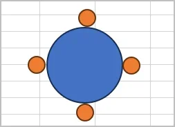
Blue = tailstock arbor or blank looking head on. Orange = indicator ball positions
Of course, whether the COAX or DTI sees gravity effect, it doesn't really matter for lathe TS realignment because we are only after any deviation on the left & right positions (3:00 & 9:00). Any gravity effects here should be the same & cancel one another. Even if measurement device was perfect, the up-down is controlled by the height of TS casting which is useful to know but something we don't change often.

1704038015957.png


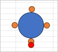
Anyways, the issue is if gravity can pull the arm down for reasons @thestelster elaborated on & as shown in my post #28 with DTI on Noga arm, then indicator ball drifts slightly (red dot) & gives false vertical center. What I can't recall on coax is if the stationary arm has any influence on where the primary reference plane is if there is such a thing.
 

Attachments

  • 1704038361500.webp
    1704038361500.webp
    3.3 KB · Views: 1
Blue = tailstock arbor or blank looking head on. Orange = indicator ball positions
Of course, whether the COAX or DTI sees gravity effect, it doesn't really matter for lathe TS realignment because we are only after any deviation on the left & right positions (3:00 & 9:00). Any gravity effects here should be the same & cancel one another. Even if measurement device was perfect, the up-down is controlled by the height of TS casting which is useful to know but something we don't change often.

View attachment 42347

Anyways, the issue is if gravity can pull the arm down for reasons @thestelster elaborated on & as shown in my post #28 with DTI on Noga arm, then indicator ball drifts slightly (red dot) & gives false vertical center. What I can't recall on coax is if the stationary arm has any influence on where the primary reference plane is if there is such a thing.
Well, yes and no. The height of the tailstock won't effect the tapering during turning greatly, but if we need to ream or drill a hole with a tailstock that's too low or high, it could create an oversize hole. (Of course extending the quill of the tailstock has to travel in the same plane (parallel) as the spindle). In the book I referenced, Schlesinger suggests a height difference between head and tail of no more than 0.0008".
 
Back
Top