Totally agree. My comments are regarding Post #27 suggesting a good use for COAX as a quick lathe TS alignment device for cross bed in/out adjustment. For example like if the TS was offset from prior taper turning & needs to be brought back in line or just spot checking. No problem there at all. I'm just saying (same as you) it would be tempting to also examine the vertical reading if it indicates TS center is high or low, but I can see potential issues as to whether the vertical reading is believable using either DTI or COAX. So bottom line is a Noga arm with DTI would work the same as COAX without gravity issues with the dial in the vertical plane on either side of TS (3:00 & 9:00 position viewing the TS head on).
-
Scam Alert. Members are reminded to NOT send money to buy anything. Don't buy things remote and have it shipped - go get it yourself, pay in person, and take your equipment with you. Scammers have burned people on this forum. Urgency, secrecy, excuses, selling for friend, newish members, FUD, are RED FLAGS. A video conference call is not adequate assurance. Face to face interactions are required. Please report suspicions to the forum admins. Stay Safe - anyone can get scammed.
-
Several Regions have held meetups already, but others are being planned or are evaluating the interest. The Calgary Area Meetup is set for Saturday July 12th at 10am. The signup thread is here! Arbutus has also explored interest in a Fraser Valley meetup but it seems members either missed his thread or had other plans. Let him know if you are interested in a meetup later in the year by posting here! Slowpoke is trying to pull together an Ottawa area meetup later this summer. No date has been selected yet, so let him know if you are interested here! We are not aware of any other meetups being planned this year. If you are interested in doing something in your area, let everyone know and make it happen! Meetups are a great way to make new machining friends and get hands on help in your area. Don’t be shy, sign up and come, or plan your own meetup!
You are using an out of date browser. It may not display this or other websites correctly.
You should upgrade or use an alternative browser.
You should upgrade or use an alternative browser.
Aliexpress Coaxial Indicator
- Thread starter neer724
- Start date
Without doing a test, I’m thinking the spring-loading of the coax stem has a far greater effect on accuracy than the gravity effect on the stem. And at even a low spindle speed the centrifugal force attempting to expand the effective stem radius will probably also be greater than gravity. But I’m only a high school dropout, so I might be wildly wrong.
The longest stem on my coax is a tapered needle, 1/8” diameter x 6” long, with a 3/16” ball end. Maybe 0.06 in3. Stainless steel, 0.27 lbs/in3 density. Math says it weighs about .016 lbs, probably less.
The coax internal mechanism will be much more likely to deflect by gravity, but it’s spinning as well, same thought on centrifugal force. My non-engineering brain says the potential gravity-related inaccuracies would be in the order of microinches.
Without doing a test, I’m thinking the spring-loading of the coax stem has a far greater effect on accuracy than the gravity effect on the stem. And at even a low spindle speed the centrifugal force attempting to expand the effective stem radius will probably also be greater than gravity.
That's my instinct too. The force required to move the needle on my coax is orders of magnitude greater than on any DTI I own.
Furthermore, I think most of what of what @PeterT found with his inverted DTI is just flex in the Noga arm system, and nothing to do with the DTI itself.
But it's always worth testing!
I cant even replicate what I did before using my Noga mini mag base on a steel plate. I cant even remember the raging discussion another forum about inverted DTI. But it must have pertained more to the arm than the indicator itself.
Just now I just threw my Noga quill arm in the lathe, rotated my 10ths DTI through 360-deg, no needle movement at all.
Then I set the DTI ball on a offshore dead center & did some readings. DTI seems to be behaving normally.
Left & Right, looks like 4 tenths runout if I believe it. Its been a year since I set it up so would not be surprising at all.


Top & Bot. This is indicating ~0.003" which seems a but high to me. I seem to recall measuring ~0.0015-0.0020" high from the get go using a few different measurement setups. Maybe I did it on the female socket side or with quill more extended or the 2 locks a bit different or socket/arbor fit or arbor circularity.. I remember chasing my tail seeing +0.001" difference just messing around. I keep hearing high is intentional but never really understood why.


Just now I just threw my Noga quill arm in the lathe, rotated my 10ths DTI through 360-deg, no needle movement at all.
Then I set the DTI ball on a offshore dead center & did some readings. DTI seems to be behaving normally.
Left & Right, looks like 4 tenths runout if I believe it. Its been a year since I set it up so would not be surprising at all.
Top & Bot. This is indicating ~0.003" which seems a but high to me. I seem to recall measuring ~0.0015-0.0020" high from the get go using a few different measurement setups. Maybe I did it on the female socket side or with quill more extended or the 2 locks a bit different or socket/arbor fit or arbor circularity.. I remember chasing my tail seeing +0.001" difference just messing around. I keep hearing high is intentional but never really understood why.
So now with these DTI pics in mind, back to my original question. What would a COAX read? If TS was 0.002" high but laterally centered on spindle axis, the needle would still be wobbling right? Now if you move the stationary arm 90-deg, does it see the lateral plane only or am I hallucinating about that? Or do you just move TS in/out until minimum +/- blur amount? (ie. indicating the raised TS but no in/out displacement).
One thing I do recall is that my TS has opposing jack screws to move laterally & lock them. I found those set screws need to be adjusted until fully tight with DTI ball on the surface simultaneously so you can see what's happening. Just a little bit of set screw retention torque is enough to displace the TS. Kind of like setting a 4-jaw chuck.
One thing I do recall is that my TS has opposing jack screws to move laterally & lock them. I found those set screws need to be adjusted until fully tight with DTI ball on the surface simultaneously so you can see what's happening. Just a little bit of set screw retention torque is enough to displace the TS. Kind of like setting a 4-jaw chuck.
I keep hearing high is intentional but never really understood why.
Tailstocks can come from the factory .002-.003 high. This is true for the LeBlond and Monarch lathes I have tested.
The reason is that the tailstock is expected to wear in, and that .002 high isn't that big a deal for all normal operations. (It induces less than 1/10th of a thou in a taper test, for instance). It will wear down to -.002, then shims are placed in the 2 piece tailstock to compensate, rinse, repeat.
Yes that's what I've heard as well. I figure I'll be dead long before 0.003" wears off. But for the sake of teeny drills & similar fussy stuff I do day to day, I actually wish the height was closer to zero.
0.003" on say a 1/32" drill represents a larger percent of over hole size deviation.

0.003" on say a 1/32" drill represents a larger percent of over hole size deviation.
Last edited:
I've been tempted to lower my LeBlond, but I found a trick: for when I really need it, I hold a tool in a boring head set to -.003. This doesn't work for #55 drills, however.larger percent of hole size deviation.
Of course I had to try this. No attempt to make sure the TS was properly aligned. My machining is usually pretty rough, and 0.001" is more than accurate enough for what I do.
Three-jaw chuck rotated by hand. Bounced a bit more when I ran it under power, but still perfectly reasonable.
Three-jaw chuck rotated by hand. Bounced a bit more when I ran it under power, but still perfectly reasonable.
Of course I had to try this. No attempt to make sure the TS was properly aligned. My machining is usually pretty rough, and 0.001" is more than accurate enough for what I do.
Was that high, low, or off to one side?
I think you have opened a can of worms @whydontu......
What effect does the long indicator shaft have on the measurement? Normally a DTI's resolution is reduced by the ratio of the standard shaft to the shaft in use. But I don't know what standard is in this case. I'm guessing it is the littlest one so maybe 10:1? If so, your 1 thou is really 10 thou. Prolly not what you wanted to hear. But we can't address things unless we know about them.
You should try it with the smaller test rod. That may require using a smaller trace on the center.
I'm not happy. I smell a giant rabbit hole.
I'm hoping to get some time in the shop today too. So I'll try and do some Calibration and perhaps start the process of defining some basic rules for using a coax indicator.
Last edited:
The COAX lathe setup is exactly how I visualized it. I would think the indicating arm length would influence the needle sensitivity, longer arm = less needle deflection? Also I don't see any adverse issue indicating under power & making the the TS adjustment set screw same time, it seems totally safe & equally convenient relative to static DTI/arm.
But anyways, what does this 0.001" tell us? The in/out is zero (on center) nut TS is 0.001" high? Or your TS height is perfect & TS is 0.001" off center? I know this is just academic because you are close enough for practical work & that is that, but just relating to discussion.
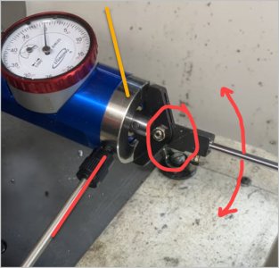
What I was also trying to remember was does the arm position have any bearing on reference plane. Red arrows show the needle swing plane. If arm was rotated 90-deg (to yellow) does it register runout relative to a different plane? My memory is rusty or maybe I was imagining things.
But anyways, what does this 0.001" tell us? The in/out is zero (on center) nut TS is 0.001" high? Or your TS height is perfect & TS is 0.001" off center? I know this is just academic because you are close enough for practical work & that is that, but just relating to discussion.
What I was also trying to remember was does the arm position have any bearing on reference plane. Red arrows show the needle swing plane. If arm was rotated 90-deg (to yellow) does it register runout relative to a different plane? My memory is rusty or maybe I was imagining things.
Attachments
What I was also trying to remember was does the arm position have any bearing on reference plane. Red arrows show the needle swing plane. If arm was rotated 90-deg (to yellow) does it register runout relative to a different plane? My memory is rusty or maybe I was imagining things.
I think the body position doesn't matter. The measurement is made on the plane of the two shoes that sweep the base of the indicator so that's the plane that matters, not how the indicator is turned. Now mind you, relatively speaking, rotating the body is the same as rotating the shoes. But still, it's the shoes that set the reference plane, not the body.
Edit - the above was stupid on my part. The shoes set the measurement plane not the reference plane. The reference is the axis of the coax indicator.
Still hoping to get to the shop today but the chances are slipping. SWMBO just informed me that I'm babysitting my 3 youngest grandkids today.
Poop. Never thought of that. More testing to be done.Was that high, low, or off to one side?
I think you have opened a can of worms @whydontu......
What effect does the long indicator shaft have on the measurement? Normally a DTI's resolution is reduced by the ratio of the standard shaft to the shaft in use. But I don't know what standard is in this case. I'm guessing it is the littlest one so maybe 10:1? If so, your 1 thou is really 10 thou. Prolly not what you wanted to hear. But we can't address things unless we know about them.
You should try it with the smaller test rod. That may require using a smaller trace on the center.
I'm not happy. I smell a giant rabbit hole.
I'm hoping to get some time in the shop today too. So I'll try and do some Calibration and perhaps start the process of defining some basic rules for using a coax indicator.
SWMBO went to get the grandkids so I snuck away for an hour.
@PeterT - As most of us had guessed, the rotation of the Coax indicator body makes no difference at all. The internal spring tension on the system overwhelms all other forces including gravity. It is VERY heavy compared to other indicators.
@whydontu. - My longest indicator probe results in almost exactly a 10:1 reduction in sensitivity vs the indicator readout scale. Since a Cone and a ball will always intersect at a single point, I used a number of simple shims to evaluate the ratio. A 2 thou shim results in a 2 tenths reading, and a 10 thou shim results in a 1 thou reading.
Using the shortest probe, the ratio is 1:4 - ie a 2 thou shim reads 0.0005. That doesn't quite make sense because the long probe is about 3 times the length of the short one. There must be some aspect of the probe leverage geometry causing that odd result. Perhaps the reference isn't the end of the shortest probe - maybe it's the probe coupling.... In any event, it's not really that important because it is a relative reading anyway. If anyone is interested, some simple geometry could establish the actual reference point.
My own tailstock is out 2 thou (based on a 2 tenths reading) in a direction toward the operator (which I will correct asap) and I cannot measure any vertical offset at all using this method. But I already knew it was vertically level within a few tenths based on other Calibration testing I have done previously. It was not high when I first brought it home and to my knowledge never was. I am the first owner. This is somewhat contrary to what others have said, but I suppose each manufacturer is different. Although I have done some huge jobs by my own standards, my regular usage is very very light. Put another way, I maybe fill 1 big garbage can with steel swarf every two years or so, maybe a bit more than that of aluminium, and a 5 gal pail of stainless and a gallon pail of brass. The only visible wear on my ways is at the joint where the removable gap is, and even that is extremely minor. All that minor usage is just my reason for believing that my lathe was built with a level tailstock- not high.
@Susquatch , you probably realize I like math without actually understanding it. Anyhoo, wouldn’t the lever arm offset affect the ratio difference between short and long lever arms? The effective hypotenuse formed from contact point at the probe tip to the contact point that moves the indicator, offset from the fulcrum.
The triangle formed by the stem and the rotating lever arm.
So we’re not actually getting a displacement measurement, just a relative movement proportional to the offset. Then the values on the dial are sort of meaningless, just need to be minimized to get as close to zero as possible. Actual measurement of offset has to be done with other methods.
@Susquatch , you probably realize I like math without actually understanding it. Anyhoo, wouldn’t the lever arm offset affect the ratio difference between short and long lever arms? The effective hypotenuse formed from contact point at the probe tip to the contact point that moves the indicator, offset from the fulcrum.
The triangle formed by the stem and the rotating lever arm.
So we’re not actually getting a displacement measurement, just a relative movement proportional to the offset. Then the values on the dial are sort of meaningless, just need to be minimized to get as close to zero as possible. Actual measurement of offset has to be done with other methods.
View attachment 42389
Yes, exactly. That's what I meant in my comment above.
In any event, it's not really that important because it is a relative reading anyway.
I confess, when I first read your note, I thought you might have caught my cosine error using a shim. I suppose I could use a ground rod with a shim to be more accurate. But your comment and mine really say it's of no consequence because it's really only relative anyway. Still, the coax indicator isn't as good as it might appear on first blush looking at the 0.0005 dial. It's ok for quick and dirty or for centering for most purposes, but other methods should be used when seeking the most precision possible.
Second test, using an 1-1/2" stem rather than the 6" stem i used yesterday. Needle deflection is greater, but maybe not 100% proportional.
It's definitely possible to identify the plane of offset, rotating the chuck by hand it's quite simple to see the needle swing and compare to the stem radial orientation.
When you see me changed the zero point on the dial, I had just retracted the TS a bit so the stem is hitting a different spot on the dead centre.
Thinking about this, the offset error is independent of the diameter of the dead centre. So it doesn't matter what size of round object is being used as the test piece.
So perfectly acceptable way to align the centre of a circular object. Just not a way to provide an accurate measurement of radial onset.
But if I wanted to screw around for hours, I could get the TS as perfectly aligned as possible, using the shortest stem, then using a proper DTI offset the tailstock a known amount and then repeat the coax test and see what the coax shows as the offset.
That seems a lots of work compared to the meatball machining I normally do.
wouldn’t the lever arm offset affect the ratio difference between short and long lever arms? The effective hypotenuse formed from contact point at the probe tip to the contact point that moves the indicator, offset from the fulcrum.
Anyone interested in math deserves a response that directly answers your question. Here is my take:
Yes, the angle of the tip to the axis also causes a cosine error. If the two probes have the same angle, then this would be a simple ratio. Of course they are not, so each would have to be calculated independently, and each would depend on the diameter of the measured object vs the axis of the coax indicator.
It's a lot to calculate to get it exactly right but it can be done with geometry. The result would be virtually nothing compared to the length induced error.
Since the majority of the above are linear relationships, it's just easier and faster to measure the difference (which is what I did because I'm lazy). Measuring the difference does the math for you (at that OD) provided you know it's not exact and is all only relative anyway.
All that said, I screwed it up by forgetting that the shim was on an angle and therefore its actual thickness as seen by the probe is greater than its measured thickness.