• Scam Alert. Members are reminded to NOT send money to buy anything. Don't buy things remote and have it shipped - go get it yourself, pay in person, and take your equipment with you. Scammers have burned people on this forum. Urgency, secrecy, excuses, selling for friend, newish members, FUD, are RED FLAGS. A video conference call is not adequate assurance. Face to face interactions are required. Please report suspicions to the forum admins. Stay Safe - anyone can get scammed.

Tips/Techniques 3DP typical machine threads

Tips/Techniques

PeterT

Ultra Member
Premium Member
This got touched on elsewhere, but I'll expand the topic here. What is the collective wisdom for printing threads in general for workshop items? I'm about to experiment & just wondering beforehand. Nothing onerous, not a 3DP trailer hitch to be sold on Ebay LOL. Mostly prototyping what will ultimately be metal. OTOH if printed threads work for the application why not use it.

- I could generate a true thread but extra work in my particular CAD app. No drag & drop vee/helix profiling like Fusion. This would theoretically make the part ready to go, but now all the other factors - accuracy of print vs class of thread, orientation of threads relative to print action, print goobers etc.

- I could spec a pilot hole only, print & tap no different than metal. But (my limited understanding) this could be bad news if the threads cut into the hole ID skin into the mushy / low density infill. So spend time in the print software to somehow increase the local hole density/thickness? is this even a thing?

- partial thread form intending to be finish tapped? (even more work)

- skip the whole thread printing thing & integrate provisions for metal thread inserts from onset?
 
Last edited:
I think a lot depends on the size of the hole and thread pitch.
A small thread like 10-32 is not really a viable thread to 3D print with any kind of accuracy. It can be tapped though.
Larger threads like 1/2-10 might work due to the size of the thread.
That said considering that the larger thread is likely to see more load the ultimate strength is a consideration.

And as you note hole orientation is a factor. I try to design such that all holes are axially oriented to the Z axis. I've never found a support style that works well for holes with axial orientation in the X or Y axis.

Personally I use brass inserts for anything that needs accurate, and durable threads.
 
Last edited:
This got touched on elsewhere, but I'll expand the topic here. What is the collective wisdom for printing threads in general for workshop items? I'm about to experiment & just wondering beforehand. Nothing onerous, not a 3DP trailer hitch to be sold on Ebay LOL. Mostly prototyping what will ultimately be metal. OTOH if printed threads work for the application why not use it.

- I could generate a true thread but extra work in my particular CAD app. No drag & drop vee/helix profiling like Fusion. This would theoretically make the part ready to go, but now all the other factors - accuracy of print vs class of thread, orientation of threads relative to print action, print goobers etc.

- I could spec a pilot hole only, print & tap no different than metal. But (my limited understanding) this could be bad news if the threads cut into the hole ID skin into the mushy / low density infill. So spend time in the print software to somehow increase the local hole density/thickness? is this even a thing?

- partial thread form intending to be finish tapped? (even more work)

- skip the whole thread printing thing & integrate provisions for metal thread inserts from onset?
I tried a fair number of threads in PET and PLA and while standard large size threads can work, I had to design special profiles to have any decent holding power on my pneumatic chisel. It took tweaking on the internal grub clearance to get a good fit

I prefer heat stake insert for smaller threads, and even used threaded insert for wood
 
In the astronomy area, printing .75 and 1.0 mm threads have been done many times. Mind you that attachments are large in diameter like 42 mm X .75. Most success has been using .1 mm layer height. Here is a link to an area I found out of 133 pages discussing threads. Check post # 793. Hope this helps.
Pierre


IMG_9533.jpeg
 
I'm sure I even have some of these heat set inserts to experiment with. I'll have to research how to increase fill density around the hole location if that's a prerequisite

@djberta when you say thread inserts do you mean a particular style? I'm also familiar with the ones with aggressive external threads like for wood etc. but assume that would be too coarse for 3DP application even if heated?
1736493244103.png
 
Peter, there are press in ones for plastic, you press them in with a soldering iron. I've thought to make some sort of stand to ensure alignment (which can be a problem) but haven't bothered yet. You can also create tight fitting hex recesses in the mate an insert a nut .... I use that a lot and think its a bit stronger

1736510460567.png

embedded hex nuts

20240331_133957.jpg


In larger sizes, printing threads is quite doable. I've made parts that thread onto a plastic water bottle for example.

With resin printing, new possibilities emerge. I've printed threaded pieces down to 1/16 diameter. They were fake, done as patterns for a lost resin casting, but they were a real helix and turned out ok - the bolt dia below is 0.060"


MWZ_9060-1300x864.JPG
 
Last edited:
If I remember right, there is a setting/adjustment for layers/rows of infill around walls, holes, openings of the object being printed. I can’t think of where to find it, think it is in the slicer, likely in the infill area. There are settings for amount, type, and I think thickness of infill. The slicer I am using has a few hundred? different fine tuning adjustments. Sometimes overwhelming, and not sure how much difference it makes in some areas.
The one I have been using is Cura or Cora, sorry have not been using the printer for some time.
You can generally set the number of walls in the strength settings portion of the slicer. Been a while since I used Cura.
Bambu fanboy now.
 
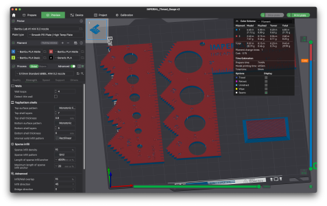
I'm only 15 years late to the 3DP party but as of a few days ago, joined the club with a Bambu A1. I prefer to say - patiently waiting the intersection of cost, quality, available time etc.
My understanding (experts will correct me) Bambu Studio is to Bambu printers, what Cura or Orca is to other brands? So it may have its ways of adjusting walls & infill & whatnot. Anyway I've just started the journey. There is much to know but hopefully it will start to sink in.

1736527074863.png
 
PeterT, Mcgyver posted them. I have a couple little sets of the inserts and press them in with a soldering iron and they work great. I like to get the longest ones that I can but i'm super cheap and buy the cheapest I can find on amazon. I have seen that you can also use some of the ones made for wood working. I have also trapped nuts inside of prints. You make the print with the area for a nut to fit, then pause at height just above the nut cut out and put the nut in and resume print.

Tom has a good video on threaded inserts and ideas for threads in printed parts.
I was just about to post this link too for that Thomas Sanladerer threads in 3d prints video. It's good, worth your time, and the comments also outline other interesting ideas.
 
You can print threads. You may need to run a tap through to clean it up. Here I am printing a thread gage using a 0.2mm nozzle. The 24 dpi gauge edge will print surprisingly well. Accurate enough to use as a gauge. So you can print threaded holes. Try it!

The problem with nozzles this small though is the print time. This print with a 0.2mm nozzle is a 5 hour print. With a 0.4mm nozzle it's 1.5 hours!

Anybody with a two head printer combining different nozzles and printing different parts of the model at different resolutions?

1736644305375.png
 
You can print threads. You may need to run a tap through to clean it up. Here I am printing a thread gage using a 0.2mm nozzle. The 24 dpi gauge edge will print surprisingly well. Accurate enough to use as a gauge. So you can print threaded holes. Try it!

The problem with nozzles this small though is the print time. This print with a 0.2mm nozzle is a 5 hour print. With a 0.4mm nozzle it's 1.5 hours!

Thanks, the video was pretty good. Modelling negative 'shape tools' to remove the required negative space for different example fastener shapes vs drawing them up from scratch is something I'm aware of but should use more.

Maybe I', not clear on the nozzle, are you saying 0.2mm to make fine resolution threads, then by default the rest of the part has to be made on same nozzle? (so nice resolution everywhere else but double print time). I had this in my mind that I could selectively print extra wall thickness around each threaded hole & that would give more meat for threading. Is that off base?

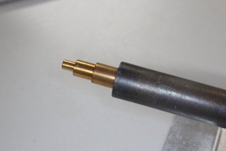
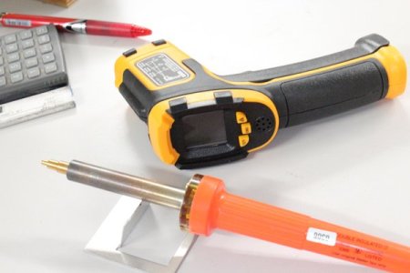
I decided to buy some heat-set to try. This kit comes with the solder iron mandrel. I have variety of irons.

1736647978276.png
 
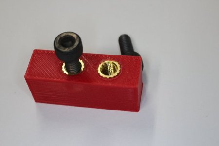
Well that was painless. Used my 40W Weller with included tool. When I read ~185C I started feeding into 3DP. Went in slowly & predictably, maybe 3 secs? When it was ~ 0.5mm proud I flipped it over & pressed it on a flat surface to make it flush. Seems sufficiently strong for what I'm targeting it for right now. Maybe someone has done a gorilla test.
 

Attachments

  • 004.jpg
    004.jpg
    18.3 KB · Views: 3
  • 006.jpg
    006.jpg
    33.6 KB · Views: 3
  • 003.jpg
    003.jpg
    18.1 KB · Views: 3
Well that was painless. Used my 40W Weller with included tool. When I read ~185C I started feeding into 3DP. Went in slowly & predictably, maybe 3 secs? When it was ~ 0.5mm proud I flipped it over & pressed it on a flat surface to make it flush. Seems sufficiently strong for what I'm targeting it for right now. Maybe someone has done a gorilla test.
Nice job.
If you need more strength orient the design such that the insert would have to be pulled through the part.
I plan to turn a few of those tips for various sizes.
 
Yes exactly. This was just testing the recommended (5.3mm) hole ID & (7mm) counterbore depth for M4 insert. I'm just showing the bolt for fun. Right now the insert is resting on the counterbore ledge & it ended up flush OK. But the real parts would have the 4mm bolt clearance from the underside so its pulling the insert into the CB ledge. Now there are situations where I may not be able to get the iron in so it would only be shear force against only the knurl. I'll figure out a tug test on this coupon,
 
Back
Top