calgaryguy
Chris
My recent (and semi-stalled by my fault) efforts on prototyping a NEMA-IEC motor adapter flange with @Janger reinforced for me the value of 3d printing.
I have a 3.25 HP Porter Cable router, model 7518. I actually have 2 of them. Most people in the wood working hobby and commercial space know of these routers for their durability and the fact the model has been around for 30-40 years. Porter-Cable, sadly, is basically a dead company and parts for these routers are discontinued/out of stock. Watching ebay is an option but its hit and miss. These routers are very heavy duty and were also sold re-badged under the DeWalt brand after DeWalt acquired some assets of PC. They are sought after in the used market and are almost a 'buy it for life item'.
The issue with one of my routers is that the plastic armature cooling fan exploded. The router is 100% fine but wont last very long without its cooling fan. Here's a pic of a similar one. Note that it has a steel ring inside it for press fit on the armature.
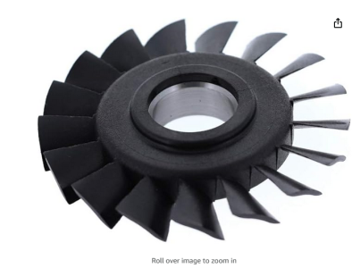
Here's pics of the ring and separated/destroyed fan plastic from my router
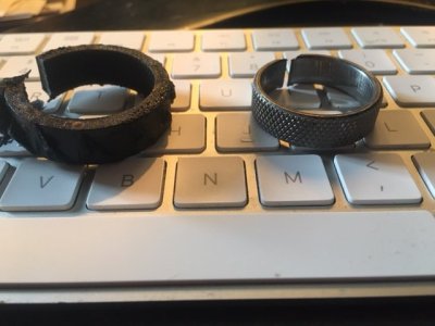
If you are cirous as to why I had to dremel/die grind the ring off - the ring had slid very close to the armature windings and I couldnt get a puller on it to remove without contacting the windings and possibly damaging the armature. At the time i was trying to preserve as much of the router as I could without damage so it could be used to parts at the very least.
The plastic fan is either molded onto, or press/shrunk fit onto the knurled surface of the steel ring. How exactly that process happens I'm not sure. The failure, if you are curious, happened when the steel ring moved slightly on the armature and made contact with the inside of the router body/housing.
SO, my question is: would it be possible to model a fan and 3d print it and attach/press onto/adhere it onto a new steel ring for this application? This router has speeds up to 28,000 rpm I think - will hobbyist 3D printed material handle this kind of speed/force? Modelling the curved shape of the blades looks to be a difficult task/ask: how would someone go about doing so?
As I stated up above, I have another, Identical router that has an intact fan - this could be used to do the modelling. Modelling the curved shape of the blades looks to be a difficult task/ask: how would someone go about doing so?
This is more a 'what if' or 'is this potentially' doable question. We can expand the discussion if its doable/possible...
Cheers,
Chris
I have a 3.25 HP Porter Cable router, model 7518. I actually have 2 of them. Most people in the wood working hobby and commercial space know of these routers for their durability and the fact the model has been around for 30-40 years. Porter-Cable, sadly, is basically a dead company and parts for these routers are discontinued/out of stock. Watching ebay is an option but its hit and miss. These routers are very heavy duty and were also sold re-badged under the DeWalt brand after DeWalt acquired some assets of PC. They are sought after in the used market and are almost a 'buy it for life item'.
The issue with one of my routers is that the plastic armature cooling fan exploded. The router is 100% fine but wont last very long without its cooling fan. Here's a pic of a similar one. Note that it has a steel ring inside it for press fit on the armature.

Here's pics of the ring and separated/destroyed fan plastic from my router

If you are cirous as to why I had to dremel/die grind the ring off - the ring had slid very close to the armature windings and I couldnt get a puller on it to remove without contacting the windings and possibly damaging the armature. At the time i was trying to preserve as much of the router as I could without damage so it could be used to parts at the very least.
The plastic fan is either molded onto, or press/shrunk fit onto the knurled surface of the steel ring. How exactly that process happens I'm not sure. The failure, if you are curious, happened when the steel ring moved slightly on the armature and made contact with the inside of the router body/housing.
SO, my question is: would it be possible to model a fan and 3d print it and attach/press onto/adhere it onto a new steel ring for this application? This router has speeds up to 28,000 rpm I think - will hobbyist 3D printed material handle this kind of speed/force? Modelling the curved shape of the blades looks to be a difficult task/ask: how would someone go about doing so?
As I stated up above, I have another, Identical router that has an intact fan - this could be used to do the modelling. Modelling the curved shape of the blades looks to be a difficult task/ask: how would someone go about doing so?
This is more a 'what if' or 'is this potentially' doable question. We can expand the discussion if its doable/possible...
Cheers,
Chris

