• Spring 2024 meetup in Calgary - date Saturday, April 20/2024. discussion Please RSVP Here to confirm and get your invitation and the location details. RSVP NOW so organizers can plan to get sufficient food etc. It's Tomorrow Saturday! you can still RSVP until I stop checking my phone tomorrow More info and agenda
  • We are having email/registration problems again. Diagnosis is underway. New users sorry if you are having trouble getting registered. We are exploring different options to get registered. Contact the forum via another member or on facebook if you're stuck. Update -> we think it is fixed. Let us know if not.
  • Spring meet up in Ontario, April 6/2024. NEW LOCATION See Post #31 Discussion AND THE NEW LOCATION

X-stop improvement for mill

PeterT

Ultra Member
Premium Member
I decided to make some better x-direction stops for my milling machine. I really like this feature for repetitive cuts or pocket milling. I never liked those little stock buttons though. Seems like if you just kiss the center post gently, they always allow a couple thou movement. I also don't want to reef down on them & over tighten the bolt for fear of cracking the cast iron dovetail.

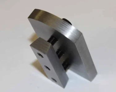
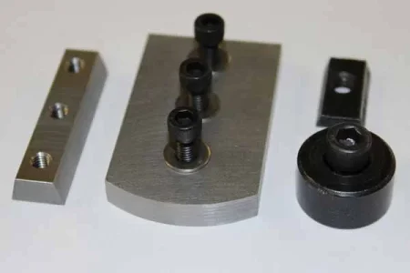
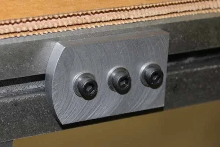
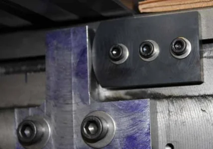
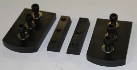
So this is my solution. Its just scraps of hot roll steel. The stops have a lot more contact area to the table edge which is what provides the grip. Three 10-32 bolts might seem like overkill but its pretty quick & they just need to be snugged up. The dovetail slider nut is a weirdo angle 15-deg chamfer. I also made it thicker so there is more dovetail & thread engagement.

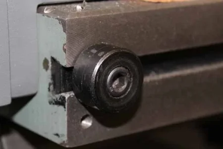
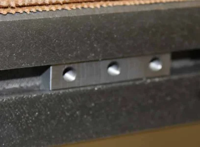
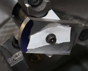
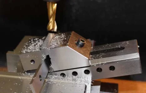
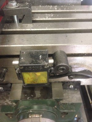
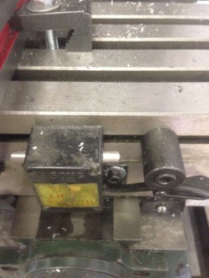
Well, I gave it a test drive today - I tried backing off & contacting a several time. The DRO shows the exact same number to 0.0005" so I'm happy. Last thing to do is blacken them. Some machining pics.
 

Attachments

  • IMG_0722_edited-1.jpg
    IMG_0722_edited-1.jpg
    26.3 KB · Views: 12
  • IMG_0720_edited-1.jpg
    IMG_0720_edited-1.jpg
    28.5 KB · Views: 11
  • IMG_0717_edited-1.jpg
    IMG_0717_edited-1.jpg
    31 KB · Views: 11
  • IMG_0716_edited-1.jpg
    IMG_0716_edited-1.jpg
    34.3 KB · Views: 11
  • IMG_0715_edited-1.jpg
    IMG_0715_edited-1.jpg
    40.7 KB · Views: 11
  • IMG_0714_edited-4.jpg
    IMG_0714_edited-4.jpg
    37.4 KB · Views: 12
  • IMG_0713_edited-1.jpg
    IMG_0713_edited-1.jpg
    36.5 KB · Views: 12

Geoff

Member
Very nice peter! I am going to make some new X stops for my mill as well. After I installed the power feed, I discovered that the stock button stops are slightly out of alignment with the electronic feed stop switch. I like your implementation and i'm sure those are VERY solid. I'm definitely going to use a few of your design ideas when i get to building mine :)
 

PeterT

Ultra Member
Premium Member
I should probably mention a few more things:

- these have nothing to do with electrically stopping or tripping a power feed off. That's a different gizmo which actually I don't use & might bite me one day if not paying attention. Its purely to provide a reliable, consistent endpoint stop between 2 arbitrary pre-set positions. As I approach the stop I slow down until it just contacts, then away go in the opposite direction, back & forth (typically increasing the depth or maybe changing a tool, whatever).

- re the nose radius operation in the lathe. The shape is give a tangent point contact where it meets the stop plate post. You can see its by design I utilized one of the mount holes in the plate as the center. Its screwed onto a chunk of stock in the lathe chuck which was faced & threaded. But I found the interrupted cutting business kind of a pain. It doesn't have a dog to prevent rotation (hence the cardboard to give it some gription). Also whacking the corners off interrupted is not kind to carbide inserts, so use HSS or something tougher. I found it much better to pre-cut the profile close beforehand & use light depth passes.
 

Geoff

Member
Hi Peter, its the same concept for my table stops (electronically though). There is a two sided switch and as the button depresses the switch, the table stops (when in power feed mode). I have attached a photo for a reference.

Before I installed the power feed, I found the exact same problem as you described.... When the "button style stops" contacted the stop point, you could still feed in a few thou at least (I have never measured but it was evident).
I would like to rig up a system that provides a solid stop, such as you did, for when i'm hand feeding and then also have something for the electronic stops. As I mentioned, and i'm not sure if you can see from the photos but the "buttons" don't line up very well with the stop switch. This is the reason why i'm planning on making something similar to what you have.

Cheers!
 

Attachments

  • Photo 2-15-2016, 2 08 40 PM.jpg
    Photo 2-15-2016, 2 08 40 PM.jpg
    1.1 MB · Views: 11
  • Photo 2-15-2016, 2 08 50 PM.jpg
    Photo 2-15-2016, 2 08 50 PM.jpg
    1.1 MB · Views: 11

PeterT

Ultra Member
Premium Member
Ah, I see now. That's a bit different than my installation. This pic shows one with the stop & (modified) center plate that is replacing the stock one. I'm experimenting with an idea to have it serve double duty for a Y-stop. Not sure that's going to pan out as planned though, its clunky. My blackening worked out better this time. I skipped the water rinse & just gave it a WD40 treatment & wipe.
 

Attachments

  • IMG_0727_edited-1.jpg
    IMG_0727_edited-1.jpg
    39 KB · Views: 10
  • IMG_0724_edited-1.jpg
    IMG_0724_edited-1.jpg
    27.2 KB · Views: 10

Geoff

Member
I think my only option is to replace the "Center plate" when I want to have a solid stop in place and then install the electronic stop when i'm using power feed. I can't really think of any other way to manage it, but really it's just 2 screws. I have not tested to see how accurate the electronic stop actually is yet. Regardless i'm going to do something similar to what you did and get rid of those "buttons" and install something more solid.

The blackening looks good Peter. I'm going to read up on some techniques and I might give it a try on my QCTP Tool holders.

Cheers!
 
Top