• Scam Alert. Members are reminded to NOT send money to buy anything. Don't buy things remote and have it shipped - go get it yourself, pay in person, and take your equipment with you. Scammers have burned people on this forum. Urgency, secrecy, excuses, selling for friend, newish members, FUD, are RED FLAGS. A video conference call is not adequate assurance. Face to face interactions are required. Please report suspicions to the forum admins. Stay Safe - anyone can get scammed.

Wheel balancing

ShawnR

Ultra Member
Premium Member
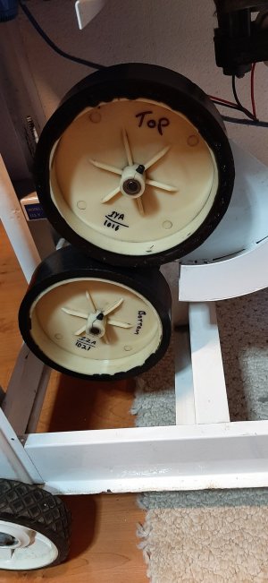
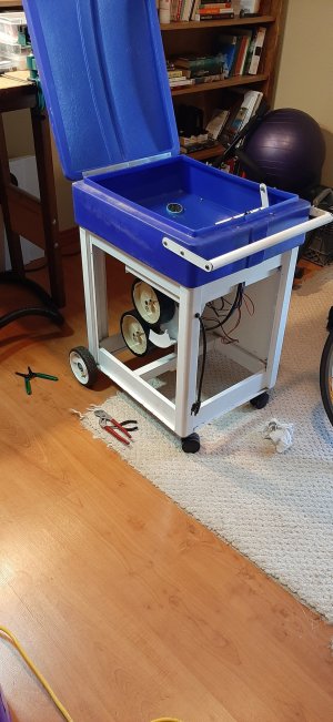
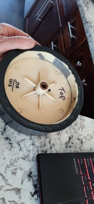
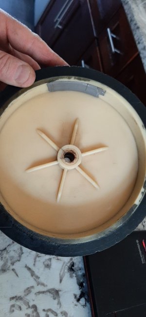
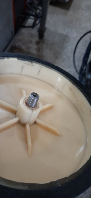
I am working on a squash ball machine, like a tennis ball machine. It has two DC motors direct driving two wheels, spinning in opposite directions. The balls drop through flaps in the feeder, down a path to the wheels, and are projected to the front or side wall to become the start of a drill of some sort. I found out it was not working. Feeling pretty handy, I offered to fix it, thinking that it would be an easy fix. What I found was one of the motors did not work, and upon disassembling it, found most of the windings broken at the commutator, where they wrap around. It was kind of bizarre. I have never seen that before. I tried to track down a replacement motor but no luck. This one appears to be a unicorn. A local motor shop said they could send it out cause they don't do motors that small but it would be several (5) hundred dollars so the project was shelved for a few years, but, recently, a friend offered to fix the motor. I thought he was going to rewind the motor but he actually repaired each break and then epoxied over them for support. It might actually work. After putting it all back together today, I found that the top wheel, the one that had the broken windings, has more vibration than the lower motor/wheel assembly. There is a metal hub but the wheels are plastic, and looks like some kind of a glued on rubber surface on them. I am thinking that the vibration might have caused the windings to break. I also wonder if the shock of the squash ball getting wedged between the two wheels, squished, and then thrown out might have contributed to it too. I don't think it is a great design, and not a great build.

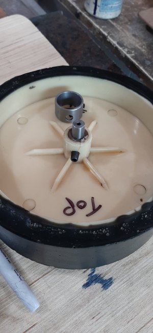
Now you have the back story. How does one balance such a wheel? Can I dynamic balance it at home or can I only expect a static balance of some sort? It looks like tape on the inside hub of the wheel and I suspect this was an attempt on balancing them, maybe weights under? The plastic that goes around the center hub, which is metal and contains the set screw have some cracks in them so I am planning on putting a sleeve over them to stop any further cracking. I have balanced lawn mower blades after sharpening but not much else in wheels. Suggestions?

I should add that I switched wheels top and bottom and the vibration followed the wheel.

Thanks
 

Attachments

  • 20220427_174926.jpg
    20220427_174926.jpg
    261.7 KB · Views: 10
  • 20220427_174936.jpg
    20220427_174936.jpg
    380.3 KB · Views: 10
  • 20220427_181415.jpg
    20220427_181415.jpg
    270 KB · Views: 10
  • 20220427_181424.jpg
    20220427_181424.jpg
    233.2 KB · Views: 10

DavidR8

Scrap maker
Administrator
Moderator
Premium Member
I think I'd make an arbour and then balance the arbour on some 123 blocks that are on a level surface. That would let you try for static balance at least.
 

Mcgyver

Ultra Member
I made a soft bearing dynamic balancer so it can be done....but for that shape, because all the mass is basically in one plane, static should be good enough. you need to rig two knife edges that very parallel and straight with enough of a trough in between to accommodate the wheel.

Whats the RPM and wheel dimensions?

Here's a static balancer for grinding wheels....one idea would be thin gauge stock stacked up and clamped to two angle plates. It comes ground fairly accurately....then put them on a level surface such as a surface plate or mill table with the wheel in between


DSCN0272-1300x975.JPG
 
There is some good vibration software for phones (given the sensors built in). YouTube some motor balancing videos and you shoukd find the software they used to set up balance.

Get it close with static first.
 

Brent H

Ultra Member
Put it on your lathe with a shaft (known to run true) and spin it with a dial indicator on it - see if you have rubber worn all oval. Might be you can take a skim off the rubber to true it up and see how things are. If the rubber tire looks “reasonably” round - check the bushing or bearing?
 

ShawnR

Ultra Member
Premium Member
Thanks guys. I will see what I can come up with today, based on these suggestions.
 

ShawnR

Ultra Member
Premium Member
I made up the stand shown in the second photo, and the axle with two center holes drilled on the lathe. The video shows the first run on it. More issues than balancing! The hubs have cracks in them but I had hoped that the metal center was ok. In hindsight, I was being overly optimistic. So I made up the two sleeves shown, heated a bit to get a snug fit over the plastic wheel hubs, hoping to pull the cracks back together and put them on. Then once back in the test stand, I found a 0.050" runout on the surface.
I have now moved to the sanding set up shown in the last photo. Although the rubber is pretty solid, I don't think it will take to cutting too well, so I am trying a sanding disc. It is making some progress. But I am sure that will throw the balance out so I will be back to trying to balance it.


Attachments

  • 20220428_120658.jpg
    20220428_120658.jpg
    201.1 KB · Views: 7
  • 20220428_120703.jpg
    20220428_120703.jpg
    468.8 KB · Views: 7
  • 20220428_165447.jpg
    20220428_165447.jpg
    252.1 KB · Views: 7
  • 20220428_175508.jpg
    20220428_175508.jpg
    333.3 KB · Views: 7

ShawnR

Ultra Member
Premium Member
I have not done anything since those photos were posted, but I have been thinking about it. I am wondering if trying to bring the outside down to be concentric with the axle is the wrong approach....? It will make the rubber thickness inconsistent so require rebalancing. Probably minor. Would it be better to try to redrill the center to be concentric with the outer circumference? The problem with that is that the center looks like a brass center bonded somehow to the wheel. And the bushing fits the motor shaft. If I mess with it, I will need to make a bushing to go into the bushing. I don't think replacing the brass bushing/hub would work as I doubt I could get any kind of a bond to the plastic to make it secure enough.

Or throw it back together as is, knowing it is crappy. But I suspect that it will just break the repaired motor again. And, putting it back together, knowing it is crappy, that would not sit well.

Any suggestions or ideas before I get grinding again?
 

YYCHM

(Craig)
Premium Member
Turn some aluminum replacement wheels and knurl the outside of the wheel rims. If that's too harsh on the quash balls then cover the rims with rubber.
 

ShawnR

Ultra Member
Premium Member
Yea, I could do that. Big chunk of aluminum. 6.75" diameter, 2" thick. I was wondering about trying to cast one. That is a last resort if a fix is not possible.
 
Top