• Scam Alert. Members are reminded to NOT send money to buy anything. Don't buy things remote and have it shipped - go get it yourself, pay in person, and take your equipment with you. Scammers have burned people on this forum. Urgency, secrecy, excuses, selling for friend, newish members, FUD, are RED FLAGS. A video conference call is not adequate assurance. Face to face interactions are required. Please report suspicions to the forum admins. Stay Safe - anyone can get scammed.

Welding cart build

DavidR8

Scrap maker
Administrator
Moderator
Premium Member
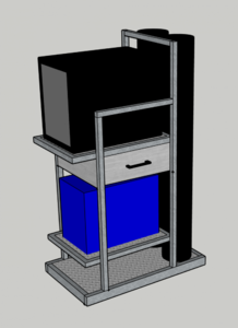
I spent some time with SketchUp last night and this morning. This is what I came up with.
I couldn't figure out how to make radius corners but I will have radius corners on the upright in front of the tanks and the front corners of the shelves.
Oh and it will have casters :D
32" long, 18" wide, 4 ft tall
Two 110 cu ft tanks
TIG on top
MIG on bottom
Side opening drawer under the TIG
Bottom shelf for TIG pedal, although I could make a bracket/holder on the side.
I didn't add cable hangers yet.
Screen Shot 2020-08-02 at 9.19.30 AM.png
 

DavidR8

Scrap maker
Administrator
Moderator
Premium Member
This pile of steel is what was previously a large warehouse cart. It has nice rounded corners which I hope to retain. I'll have to narrow the parts but hey, I need the TIG practice right?
Steel for cart.jpg
 

YotaBota

Mike
Premium Member
Stacking is a good way to save space. Any idea what the total weight will be? I'm thinking of the load on the casters from the cart.
 

DavidR8

Scrap maker
Administrator
Moderator
Premium Member
Stacking is a good way to save space. Any idea what the total weight will be? I'm thinking of the load on the casters from the cart.

Tanks x2 = 150 lbs
Welders x2= 85 lbs
Stuff x 1 = 10 lbs
So all in maybe 245 lbs?


Sent from my iPhone using Tapatalk
 

Bradells

(BRad)
...
I couldn't figure out how to make radius corners but I will have radius corners on the upright in front of the tanks and the front corners of the shelves...

Here's a quick way to do your rounded corners. A little different from your approach, but can also be done another way (will do a second post). The tool of importance is the "Follow Me" under the "Tools" menu.

I'll dub this 'The Abstract Way'

Step 1: Start your layout of either the inside or outside dimension of your Top view.

Screen Shot 2020-08-03 at 6.52.22 AM.png

Step 2: Add in your bends.

Screen Shot 2020-08-03 at 6.52.37 AM.png

Step 3: Switch to a Front view and draw your material profile.

Screen Shot 2020-08-03 at 6.53.33 AM.png

Step 3a: (Extra bonus round) Add in the radius of the material... **This will require an extra step later on**

Screen Shot 2020-08-03 at 6.53.47 AM.png

Step 3b: (Still extra bonus round).. Select the stuff that doesn't need to be there (inside radius, corners, etc) and delete them

Screen Shot 2020-08-03 at 6.54.04 AM.png

You should be left with something like this.

Screen Shot 2020-08-03 at 6.54.39 AM.png

Step 4: Do the same for your Top view (can be done as part of step 1 ... this is just the order that I did it in to keep things congruent)

Screen Shot 2020-08-03 at 6.54.57 AM.png

Step 4a: (Bonus round extra required step). You will need to OFFSET the top view profile to touch the edge of your material profile .... otherwise the Follow Me tool won't work.

Here you will notice that the outside profiles don't touch. You will have to clean up and add in a line segment to make everything 'touch'.

Screen Shot 2020-08-03 at 6.56.22 AM.png

OFFSET the profile to touch the edge of the radius.

Screen Shot 2020-08-03 at 7.00.56 AM.png

Step 5: Select the material profile created in step 2. Under Tools, select Follow Me, and Drag the profile around your path.

Screen Shot 2020-08-03 at 6.57.03 AM.png

Going around the bend.

Screen Shot 2020-08-03 at 6.57.20 AM.png

You should end up with this.

Screen Shot 2020-08-03 at 6.58.04 AM.png


Stay tuned for a different approach of doing this ...


Brad
 
Last edited:

Bradells

(BRad)
So here is method #2

This method would seem easier to do .... as you are just 'filling in the gap', but Sketchup has a hard time with it (and I have a very hard time with SketchUp with it, so I do my earlier 'abstract' method .... if anyone knows a better way to do this type of workflow, please share)


Step 1: Draw your straight pieces.

Screen Shot 2020-08-03 at 7.15.40 AM.png

Step 2: Draw out some construction lines from the edges of your profiles.

Screen Shot 2020-08-03 at 7.16.55 AM.png

Step 2a: Make sure they are equidistant apart. (The tape reading didn't show up in the screen shot)

Screen Shot 2020-08-03 at 7.17.29 AM.png

Step 3: Add in your radius.

Screen Shot 2020-08-03 at 7.18.26 AM.png

Step 3a: Delete out what isn't needed.

Screen Shot 2020-08-03 at 7.18.35 AM.png

Step 4$@(#. Use the Follow Me tool ......

Screen Shot 2020-08-03 at 7.19.17 AM.png

Screen Shot 2020-08-03 at 7.19.52 AM.png

Screen Shot 2020-08-03 at 7.20.08 AM.png

Screen Shot 2020-08-03 at 7.20.30 AM.png

Screen Shot 2020-08-03 at 7.20.52 AM.png


As you can see, it's hard for Sketchup to know what to do at the end of the line segment. Does the user want it to turn around that end of the line? Partway? Follow another contour path?


This is where I like to do the previous version, less things for SketchUp to assume. (Sketchup does a great job at assuming many things, where in space the mouse is in relation to other objects .. snapping/moving/drawing/etc ... but not this). You can slice up the 'tubing' into parts later if you'd like.


Brad
 
Top