Understanding Motor Connections on a RF-45 mill/drill

Downwindtracker2

Well-Known Member
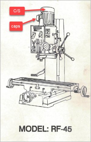
Any idea of what these connections go to ? And how to find out ?

l'm Looking to be able to learn about wiring the motor on my RongFu-45 mill/drill . I bought a couple of well used Taiwanese machines, a DF1224g lathe and the RF-45 . Just $1700 for the pair. Used RF-45s were going for at least $1500 at the time. . Obviously, they had problems, both had mickey mouse electrical repairs. The lathe got a Baldor 3phase 2hp and a Hitachi VFD . I'll use the mag starter off the lathe and a SquareD drum switch for reversing. Both are 2hp rated. The motor is a " Capacitor AC Induction Motor" 2hp 1ph 1725rpm 10.5amp 2001 date. I have 220volts.

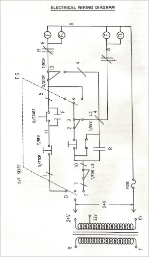
I'm a 73 old retired millwright and am willing to learn something new. At my age it's pretty slow learning, though, chuckle. Not like half a century ago. Once you understand something, it's simple .I ,then, can follow a schematic . I know single phase motors work start with starting windings and have run windings . BTW computers are not on my list of skill sets, so I'll just have to list the input wire colours and pins with their motor wire numbers on the junction box six pin block.

top row
white- #6
yellow-#1
----- #5#3#2 connected together
bottom row
red-#4
not used
black- no number

What do these wire numbers go to? These were on the inside of the lid.

There is a circuit breaker. I wonder what it connects between ?

The previous owner had a light switch hooked up, as I said, it was mickey mouse. I used the drum switch as on/off and followed his wiring. She has almost paid for herself. But it's time to fix the electrical problem and some more of the mechanical issues. I think it had been CNCed before he got it. He was a cabinetmaker and used it on some design run.
 
Sorry to say single phase and 3 phase are different animals. The VFD and its motor, leave them well
enough alone, they'll out perform the single motor and you can control the speed on an AC motor. :D.

As to the single phase motor, I've had both a a drum switch for reversing and a single toggle switch for on and off, prevent the motor jumping in the mounts when switching it off and over shooting.

So don't get too confused.
 

Downwindtracker2

Well-Known Member
The lathe motor/ VFD is wired in, it still needs programing but it does runs. Hitachi manual is worded very industrial. And is 276 pages long, English only. But that's another problem for another day.

The mill/drill motor is just a four pole single phase. To wire in the mag starter I was helped by a Keith Rucker YouTube video. Mind you, the control box looks like a plate of spaghetti , chuckle.
 

Susquatch

Ultra Member
Administrator
Moderator
Premium Member
First of all, your first post is confusing. I can't tell if you are talking about your mill or your lathe since they are mixed together even in the same paragraph. You know what you mean, but we don't. Please make separate threads for the mill and the lathe. I'd suggest a new thread for the mill since your priority seems to be the lathe.

Please take a photo of the inside of that box on the motor. Baldors are good motors. I don't think you need to touch it. But to answer your question, we would need to see a photo.

Don't disconnect anything. Figuring out motor wiring can be easy or a total bitch depending on how well the wires and connections are labelled. The wires on my motor were labelled but very poorly. I needed a magnifying glass to read them. But since your motor works as is, there is no need to read them or worry about them.

I'd also suggest getting someone else to look at it. I'm a few years older than you and love learning new things too. But I'd like to live at least another 10 years so I'd start learning electrical with 12V systems before I took on 120 or 240.

That might all sound a bit harsh, but again, I'm a few years older than you so I think I know where you are coming from and can empathise with your needs. I mean well.

Where are you located? Maybe another member can help?
 

Proxule

Ultra Member
I was going to say the same, Send photos if possible and where are you located ( seems you are from BC ).
We will help !
 

Downwindtracker2

Well-Known Member
Good Morning Guys

Sorry,long and confusing questions are my specialty .

On another forum, I got the information pins 1 and 6 are switched for direction change . pin 4 is a constant. He also provided a schematic for use with my drum switch.

The SquareD drum switch I purchased at Princess Auto is a 2601 model. I've learned it's a "chopstick style" . Basically a 3phase unit. There is "hockey stick style" of drum switch, too. .

This morning I taped off the power leads from my contactor and plugged in. The power on light came on . It is supposed to be switched along with the main power. I see some quality time with my multimeter today tracing connections. oh well.

I very recently gave up my flip phone for a hand-me-down smart phone, so getting photos on the computer is not going to happen. I'll spend the time learning machining, fun and useful , and I will have to program my VFD. I even had to learn to program the arc on my welder, for heaven's sake.
 

Susquatch

Ultra Member
Administrator
Moderator
Premium Member
On another forum, I got the information pins 1 and 6 are switched for direction change . pin 4 is a constant. He also provided a schematic for use with my drum switch.

Dangerous assumptions if you ask me.

Any two of the 3 wires of a 3 phase motor can be switched to reverse direction. There isn't just two and two only. Or you can leave them all as is and let your VFD reverse the motor.

There is no such thing as "constant" in a 3 phase motor. The closest I could suggest for that would be a ground wire. At least that's the only one you would never change - which is the only reason I'd use the word constant. That word doesn't belong in a motor connection. I'd bet the correct word they used is common, not constant. But as I said before, any two can be reversed.

You don't need or even want a drum switch with a VFD. And you definitely want a VFD.

Assuming you are correctly quoting what you heard, your other forum contact isn't a very good source of information.

I'm probably not coming across very well here. But I'm trying to be as honest and blunt with you as possible. I simply cannot advocate playing around with 220V wiring if you are not familiar with it. My spidey senses are screaming at me that you are running a very high risk of getting hurt, or worse.

I really think you need a visit from someone who knows what they are talking about.
 

phaxtris

(Ryan)
Premium Member
Premium Member
I think we need to start from square 1

Your working on the mill/drill right now correct?

What motor is on the mill drill, the single phase motor or the 3 phase motor, and what motor are you trying to put on it

From your original post it sounds like you are trying to wire up the mill/drill with the single phase 220 motor ??

I think everyone is very confused as to what is going on here, and no one wants you to get electrocuted
 

Downwindtracker2

Well-Known Member
I do know about how simple 3phase motors are to reverse. With jammed up waste conveyors in sawmills it was a common way of freeing them up . Go to the MMC, open the cabinet, change two wires, run the conveyor backwards. But this a single phase. These common RongFu-45s make good garage sized mills. We had one in our maintenance shop at work , my gunsmith has one. The VFD is on the lathe.

Today's time with the multimeter has shown the use of the contactor that I took off when I did the lathe conversion, is not going to be simple. It's going to take some wiring changes. It's do-able . Luckily, it's pretty crude, it came off a' 92 Busy Bee lathe. But, hey, I'm learning something new.

I have always been leery about opening cabinet doors. I always felt sparkies were disposable. Let them do it. I have only met two I liked. But that's millwright a prejudice.

I guess I should add some background . The RF-45 mill/drill was so cheap because it had been converted to CNC and the previous owner after he purchased it, had difficulty putting it back to manual. That is what I surmised when I got into her . The feed screw wasn't anchored at one end, the feed screw and the nut were so worn there isn't any adjustment left. The control box was empty. He used a light switch to run it. It only went forward . One of gears howls. I will have to check the dovetails .

I only live half an hour from the Bellingham Grizzly store so I bought a feed handle for a RF-45 clone and got the table working. A drum switch from Princess Auto got rid of the light switch, It has done enough work to almost pay for itself, but not the tooling. It's time for another bout of fix, first electrical. I have new feed screws and nuts from RongFu so that is next up. For now I will leave the gear, pulling apart a gearhead is pretty major. I don't have the tools to scrape the bed so all I will know is the wear numbers.
 

Downwindtracker2

Well-Known Member
I think I sorted out the motor control wiring. Before installing, I tested the motor by hooking up the motor to a switched leads using pin # 4 as a constant and changing #1 and #6 and only got a hum on either set up. . So I took the motor off . Someone had been here before me., they used copper Nerv-Sieze. Time to take it to motor repair shop. Motor rebuilding is beyond my skill level.
 

PeterT

Ultra Member
Premium Member
@Downwindtracker2 I had an RF-45, single phase, 220V (1998-ish vintage). The manual isn't exactly what I'd call rich with electrical information but here you go FWIW. I also know that later RF-45's (both Taiwan & then China made) had quite different wiring & controls, so this may be of zero value. Saying RF-45 is like saying 'car'.

One thing I haven't heard you mention are the start/run capacitors or centrifugal switch. I never had issues with mine so never went digging, but that is a very common area for things to go wrong with these kinds of motors & machines. A hum or cogging sound may be a symptom, but not necessarily so. Smarter electrical people than me on the forum can guide you how to test. I suspect the centrifugal switch is under the motor end bell cap. My parts sheet doesn't show anything in this regard, but logically that's where it would be.
 

Attachments

  • EDT-2022-12-14 8.55.05 PM.jpg
    EDT-2022-12-14 8.55.05 PM.jpg
    56.5 KB · Views: 12
  • SNAG-2022-12-14 8.52.47 PM.jpg
    SNAG-2022-12-14 8.52.47 PM.jpg
    86.3 KB · Views: 16
  • SNAG-2022-12-14 8.53.34 PM.jpg
    SNAG-2022-12-14 8.53.34 PM.jpg
    244.6 KB · Views: 12
  • SNAG-2022-12-14 8.53.58 PM.jpg
    SNAG-2022-12-14 8.53.58 PM.jpg
    177 KB · Views: 11

Downwindtracker2

Well-Known Member
Good Morning

This RF-45 is a genuine RongFU. Thomas Skinner imported it and sold it under their house brand Advance. It was through them I got the feed screw parts. I remember when Thomas Skinner was down on Main St, just up from the CN rail station. Right in the center of Vancouver's False Creek industrial area. They had a small retail store. I got my Record vise and Hazet tools from them. They were the largest machine shop supplier in BC. Now they sell industrial CNC machines.

The importer King Tools has a flyer out, mine came with a KBC order, A Chinese RF-45 clone is $ 6499 with a stand at $399. I made a point of showing my wife. At work when a small motor,a 2hp is small, packed it in, it wasn't worth it to repair it. There are a couple of motor repair shops close by, even Tedco is close. I have no idea of the motor frame #, either. I'll see what they say.
 

Downwindtracker2

Well-Known Member
I just got back from a nice visit with a motor rebuilder .He gave me a phone number of a guy who does small motors. He told me about the economics of motor rebuilding . For even standard industrial motors the cross over was about 100hp. He specialized in European metric motors.

What has me suspicious , is that someone has been here before me. Pulling a flange mounted motor is always a pain , the motor shaft almost welds itself to the gearbox input hole. I have steel feather wedges just for that. A couple of large screwdrivers was all that was needed. That is much too easy.This motor might just have an issue, making the motor connection moot.

Here is millwright trick for getting those allen headed cap screws out, mine were only snug and not tight. The motor almost covers them. Mine took an 8mm , so I cut a piece of 5/16 allen wrench. I have a number of 5/16 ones. You can break them free with a quality Crescent wrench, then use a ratcheting wrench the rest of the way. I'm not sure if a Gearwrench head is small enough.
 
Last edited by a moderator:
Top