Understanding machinist layout with DRO better

justin1

Super User
So I'm planning trying to build my own D1-4 back plate for a 4 jaw chuck I've had laying around for ever. So I decided to fool around with layout with DRO whole I wait for my collets to show up. My DRO is only 2 axis but it does have a bolt hole circle function which is great makes making the 3 cam lock pins holes much easier but I'm not sure how how to lay out the retainer cap screws using the DRO with out manually zeroing each hole and using the bolt hole circle function to index each cap screws hole was hoping to lay out everything from central point to help with any errors. Probly not needed but would like to learn how to maintain accuracy and consistency. (I don't own rotary table yet so indexing with DRO is currently best method for me atm)

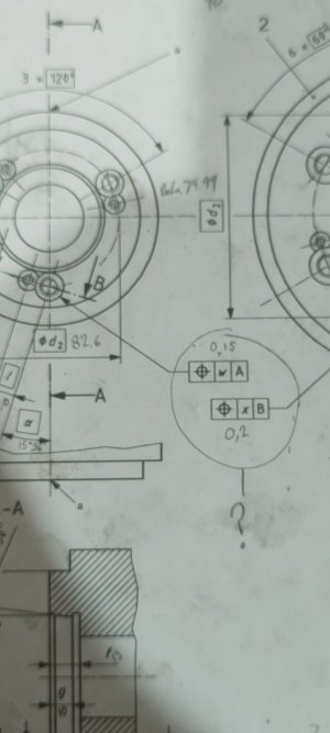
I also don't understand fully what the blueprint detail I've circled in attach picture is referencing. From what I found on symbol syllabus that bullseye means position but not sure what position that really means in conjunction to the information it's provided.

I've attached the prints I will be working off to make it easier to follow along with my question and possible more questions if I run across something along the way. I would appreciate some advice and look forward to learning more.
 

Attachments

  • IMG_20230217_152224362.jpg
    IMG_20230217_152224362.jpg
    131.2 KB · Views: 19
  • 73724-ISO-702-2-2007Cor-1-2009.pdf
    270 KB · Views: 14

PeterT

Ultra Member
Premium Member
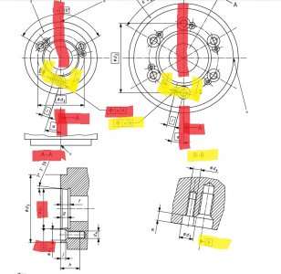
Your drawing is just cutting it off but almost looks like the retainer hole is stepped offset relative to that angle (15-deg ++) of the pin hole, which is at some centered diameter. Personally I would dial the plate to the center hole 0,0 & (spot/drill/ream) them all using X,Y coordinates relative to center in the same setup. Minimizes errors IMO. Many of us have tools to make you a dimensioned CAD drawing to whatever number of significant figures you like with the appropriate information in hand. Sorry I don't know what the symbols mean, counterbore head clearance maybe? I had some very detailed camlock drawings at some point but they are MIA. I think it came from some kind of spindle summary, not a chuck provider.

1676685646778.png
 

phaxtris

(Ryan)
Premium Member
Premium Member
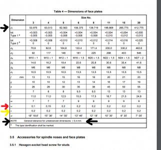
Looks like to me that "O w A" is giving you the tolerance of d1 In detail/cut A-A and O x B is giving you the tolerance for location of the larger of those two holes, marked B in detail/cut B-B

The table with the tolerances is on the next page in that document
 

Susquatch

Ultra Member
Administrator
Moderator
Premium Member
Looks like to me that "O w A" is giving you the tolerance of d1 In detail/cut A-A and O x B is giving you the tolerance for location of the larger of those two holes, marked B in detail/cut B-B

The table with the tolerances is on the next page in that document

I agree. That was my take too. But you are faster than I am. No corrections from me!

Your drawing is just cutting it off but almost looks like the retainer hole is stepped offset relative to that angle (15-deg ++) of the pin hole, which is at some centered diameter.

Peter, download the pdf in the link. It has the full drawing in it.

Phaxtrix beat me to the interpretation, but I like your suggestion better than what is in the drawings and specs. Never let the perfect be the enemy of the good.

Also, the download is a great source for the data you lost. I've added it to my files for that reason too.
 

phaxtris

(Ryan)
Premium Member
Premium Member
You may already know this, but just in case...

One thing i might suggest to help avoid fabrication errors. Print out the relevant drawing and actually write in the dimensions on the paper instead of the variable, don't rely on checking the table for the dimension while your "in the heat of it", chances are you may look at the wrong line and before you realize it have gone to far.

At least that is what I do, i have made those mistakes before, it sucks
 

PeterT

Ultra Member
Premium Member
Peter, download the pdf in the link. It has the full drawing in it.
Aha, how did I miss that. Good document.

In another discussion someone downloaded a solid model & apparently it checked out to official dimensions (random example). But I am loathe to recommend this. I've also seen some other stuff that was complete garbage.


justin1

Super User
Thanks for the info on what the symbol means I was confused on what they meant. That link @curmudgeon did a great job as clearing up anything I had about that.

@phaxtris haha ye I always try to keep non relevant numbers/prints away from what I'm doing cuz it is very easy to mix them up. And I scribbled out the other info for the other chucks so I could double check the numbers I was filling out in data spots. These prints have a different layout then what I'm used too as welder.

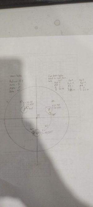
So I have attached drawing of what I'm currently doing to find all 6 holes on DRO. Makes sense to me but may not to everyone lol... But there has to be way to find circumference of the cap screws holes from the plans I have. But I feel like I'm missing a measurement to find it. Would be lot easier to use just the one center for both layouts.

Radius- ??
(No where on drawing mentions this for cap screws from center of workpiece that I've seen on the 11mm from center of main holes)
Holes- 3
(Easy to figure this one out)
Alpha- 0???
(Not sure what this does yet)
Beta- 90° + 15.01°
(rotates holes I figured out.)

Update:
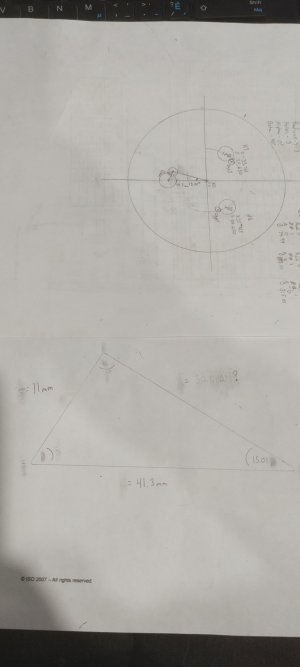
Actually currently trying to figure out Irregular Triangle trig stuff think I can find the radius with math... Yeay fun a subject I did very poorly on lol
 

Attachments

  • IMG_20230217_205004086.jpg
    IMG_20230217_205004086.jpg
    105.4 KB · Views: 7
Last edited:

curmudgeon

(Steve)
I'll take a stab at this, and am very ready to learn I did it wrong...

Starting at your bottom stud, you located it at (0, -41.3).
The adjacent cam is 11.0 mm away @ 15° 36' or (15 + 36/60 = 15.6)°
The y offset is sin(15.6°) * 11 mm= 2.96 mm
The x offset is cos(15.6°) * 11 mm = 10.59 mm
So that cam would be located at (-10.59, -38.34)

I can continue on to calculate radius and other positions if you want.
 

justin1

Super User
I'll take a stab at this, and am very ready to learn I did it wrong...

Starting at your bottom stud, you located it at (0, -41.3).
The adjacent cam is 11.0 mm away @ 15° 36' or (15 + 36/60 = 15.6)°
The y offset is sin(15.6°) * 11 mm= 2.96 mm
The x offset is cos(15.6°) * 11 mm = 10.59 mm
So that cam would be located at (-10.59, -38.34)

I can continue on to calculate radius and other positions if you wanted

Don't have a clue how you got this numbers like witch craft too me is there a resource to do what you did? I got about this far(attached picture) with the trig stuff before realizing I don't know how the alpha beta stuff works with the letters and would solve what I thought was c and then use that to find angles of 2 missing sides just to get errors lol...

I let the DRO do that math for the first 3 holes I just used what was on drawing and input into dro lol so was trying to find the other radius and let DRO do hard part


Edit: noticed I screwed up on degree when I transferred data to drawing I wrote 36" not 36'

Update:

If I understand this right my other cap screws should be at

X+46.355
Y-17.69

X-25.175
Y+23.61

X-10.59
Y-38.34
 

Attachments

  • 16767007815544526582890086671569.jpg
    16767007815544526582890086671569.jpg
    103.2 KB · Views: 6
Last edited:

curmudgeon

(Steve)
In your sketch, it looks like you're trying to calculate the radius of the cam hole centres
You have 2 options to calculate the length of that leg of the triangle.

1) use Pythagorean Theorem, i.e. a2 + b2 = c2 where a and b are the lengths of the legs of a right-angle triangle and c is the length of the hypotenuse, so (41.3)2 - (11)2 = 1,584.69; take the square root and the length of the missing leg is 39.8

or
2) use trig, you know the length of the hypotenuse (41.3 mm), and you know the angle (15.6); the cosine of an angle is defined as the ratio of the length of the adjacent leg / length of the hypotenuse; so cos(15.6) = r/41.3, and r = cos(15.6) * 41.3 = 39.8
 

justin1

Super User
Ye that's what I was trying to do but ended up with 30.08073 sooo I was doing something wrong for sure. Going to have to study up on how that works because I don't have a clue what hypotenuse means or how the sin cos tan work. I tried to follow along with a video but kept getting different answers. Then tried those online calcs but they kept giving me 2 different options. The only advanced math thing I use is the 3/4/5 method everything else is usually done for me on the blueprints or if field fitting something cardboard and various other tricks to make things work with out math :(

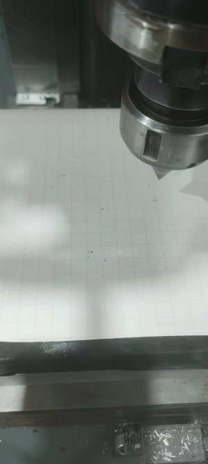
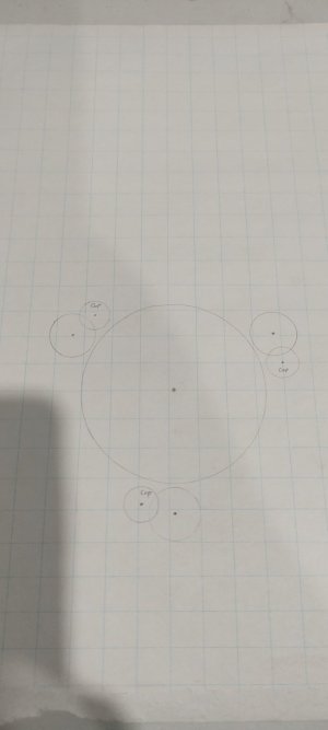
I used the 39.8 with the DRO and
Radius: 39.8
Holes: 3
Alpha: 0
Beta: 105.6°

And that seemed to work I think? Looks correct lol if that means anything.
 

Attachments

  • 16767046013473095012487375906902.jpg
    16767046013473095012487375906902.jpg
    136.3 KB · Views: 8
  • 16767088907964249839763018156117.jpg
    16767088907964249839763018156117.jpg
    103.8 KB · Views: 5
Last edited:

Susquatch

Ultra Member
Administrator
Moderator
Premium Member
@justin1 - others have done a good job of doing the math for you. I'd prolly just confuse you if I did more.

But I have a saying that I love. "If you give a man a fish you feed him for a day. But if you teach him to fish you feed him for a lifetime."

I'd highly recommend that you go and buy or borrow a good basic geometry and trigonometry book and learn the math. It isn't hard stuff. But it's pretty basic knowledge that all machinists need. Just get a simple book that has the information and examples in it. Maybe some quizzes so you know you have learned what is there.

I don't have such a book to recommend, but maybe other members do.

When you are done learning that basic stuff, get one on basic algebra too. It's an equally important field of mathematics that everyone should know. You may already know basic algebra, but I thought I needed to include it just in case you didn't.

If you learn the basics of these subjects you will feel empowered and more confident of your machining activities and you will find the knowledge and skills useful in many other areas of your life too.

BTW, you are not alone. It seems our schools are not doing a very good job of teaching this stuff anymore. I think that's wrong, but it seems that I don't get a say on it. You can't change the school system either, but you do get to change your own abilities if you want to.
 

DPittman

Ultra Member
Premium Member
It seems our schools are not doing a very good job of teaching this stuff anymore.
You know I've said that also but I also know that they are teaching mathematical concepts and stuff I did in university almost 25 years ago to high school students today.
 

Susquatch

Ultra Member
Administrator
Moderator
Premium Member
You know I've said that also but I also know that they are teaching mathematical concepts and stuff I did in university almost 25 years ago to high school students today.

I could go on and on and on and on and on about this trend. In my view, it's a horrible mistake. Here is my 100,000 ft up view.

Teachers like to teach smart kids. Smart is usually defined as kids with good memories. But not all bright kids have good memories. The creative innovative common sense kids get lost in this process.

Just focussing on math (because that's the topic of this thread), those who have great memories do well on tests that require a good memory of formulas and equations. But that does not even remotely suggest they actually understand the underlying principles. If the exam questions are the same as the memorized material, the result is good grades. Ask them something not in the material that requires understanding and they do poorly.

Too many of the kids who have the horsepower to actually understand are left behind.

Yes, it's impressive to watch a grade 8 kid do calculus or a grade 10 kid do differential equations. But I've asked those same kids what the questions and answers really mean and the vast majority have no slightest clue.

It's so sad to see a really bright handy practical kid get crappy grades, and become hopelessly lost just because they cannot remember a thousand formulas. And quite frankly, it's equally sad to see so many really stupid people running the show (or teaching my grandkids) just because they got great grades based on their memories instead of common sense, practical abilities, creativity, and intelligence.

OK, I feel better now.
 

phaxtris

(Ryan)
Premium Member
Premium Member
I have to do trig often to get workable numbers from drawings for layout, I just use an app on my phone, there are lots of free ones and they provide you everything, not just one variable...plus chances are i would make a mistake doing it by hand...which could cause a mountain of work later

Math teachers from what i remember, sucked, like @Susquatch said, they only focus on memorization of things that are at that stage in life, very abstract, no practical explanation. So the kids that are good at memorizing do well, the ones that don't, don't. At that age that usually means the girls are at the top of the class and get all of the attention and the boys are left in the dust :(

You know what i think is the worst thing about high school math.... none of them cover anything about income tax, household budgeting or intrest, the number of guys that have told me "i will make less money if i work overtime/get a raise because it will put me in a higher tax bracket" is astonishing
 

Susquatch

Ultra Member
Administrator
Moderator
Premium Member
the number of guys that have told me "i will make less money if i work overtime/get a raise because it will put me in a higher tax bracket" is astonishing

My favorite way to express this goes like this. "I wanna be the guy who pays the most taxes in the whole country".

Ironically, this past year was one of the worst farming years I have had since I started. But because most of my capital has been depreciated and because I anticipated a low yield and spent less on inputs, my profit was higher than normal which means I will have to pay more taxes this year. Whenever I gripe about that I just remember, "I wanna be....."
 

phaxtris

(Ryan)
Premium Member
Premium Member
@Susquatch I like your train of thought! The more you paid the more you made.....look that even rhymes!

Edit....on a side note.....man some of you guys are up late! i woke up the morning, posts at midnight! dedication!
 
Last edited:

curmudgeon

(Steve)
I used the 39.8 with the DRO and
Radius: 39.8
Holes: 3
Alpha: 0
Beta: 105.6°

And that seemed to work I think? Looks correct lol if that means anything.
That's really cool that you can use the DRO to mark out your layout like that. If each pair of centres measure 11 mm apart then it looks like you nailed it; nice!
 
Top