• Scam Alert. Members are reminded to NOT send money to buy anything. Don't buy things remote and have it shipped - go get it yourself, pay in person, and take your equipment with you. Scammers have burned people on this forum. Urgency, secrecy, excuses, selling for friend, newish members, FUD, are RED FLAGS. A video conference call is not adequate assurance. Face to face interactions are required. Please report suspicions to the forum admins. Stay Safe - anyone can get scammed.

Turning the thread on a chuck mounting plate

SparWeb

Active Member
Hi
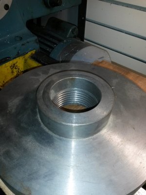
When I got my lathe last year, an unused chuck mounting plate was included with it. It's unfinished because there are no holes drilled yet for mounting anything, but I'd like to mount a 4-jaw chuck on it.
Trouble happens because the threading was started to match my lathe's spindle, but it wasn't finished either. I can start threading it on, but only about 1 turn which is nowhere near far enough for it to lock in place.
I've tried re-cutting the thread, but it barely fits in my 6" chuck - not securely enough for me to try anything. This may be the reason that the thread isn't finished, but I can't really tell.

Is anyone here able to & interested in trying to finish threading this chuck plate for me? If you agree that the set-up, turning, and measurement of the threads should take at the most 2 hours, then we can do business.
I think you'd need a lathe with at least an 8" chuck to grip this thing. Fair warning, the surface finish isn't great, so it may be some kind of cheap hot-rolled plate. It's worth trying, but not worth a heroic effort.
If you can't see my bio information, I'm near Calgary, Alberta.

Basic dimensions:
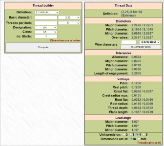
Spindle thread: 2-1/4" - 8 tpi
Plate OD 9.5"
Shoulder OD 3.5"
Total thickness 2 inches
 

Attachments

  • 20210102_165925 - Copy.jpg
    20210102_165925 - Copy.jpg
    274.7 KB · Views: 11

Susquatch

Ultra Member
Administrator
Moderator
Premium Member
Im a bit too far. Shipping alone would kill you.

But, I can't help thinking about other ways to do it.

Can't you chuck it on the hub/shoulder? Surely your 4 jaw will open enough for that! And I assume you have tried reversing the Jaws......

Have you looked for a tap that big? Your local farm supply place might have one or might lend you one.

Just ideas.
 

PeterT

Ultra Member
Premium Member
If you don't generate any volunteers, the 'throw money at it solution' might look like options below as a base $ reference. Location & shipping cost seems to be the challenge with this stuff. They might use the phrase 'semi-machined' but what that typically means is the threads are complete. Leaving the remainder of face/OD/hole pattern features to you which is what you want anyways.

I haven't done much existing thread chasing so maybe others can chime in. But I can envision some potential 'time detours' getting your existing one to order. If its a 'simple' matter of deepening the existing threads to fit, I would think one would need the male counterpart handy to test progression/fit? Unfortunately, that's still attached to your lathe LOL. That's why some guys turn a male dummy first which they can validate PD & use that against the internal thread. If your job #1 was held slightly different than job#2 or maybe slightly different cutter tool geometry between them, that might factor into results as well. 2 hours doesn't sound like much but I seem to work at frozen snails pace on the best of days.

Just wondering because I think some forum guys have made their own spindle threaded accessories - did you thread to a target depth referencing off the bore ID (only) or how did you establish fit, presumably without removing part or internal PD measurement device?
 

Johnwa

Ultra Member
@PeterT I made a spindle gage and use that as a trial fit when getting close. Even with that I’m likely only about 50% successful in getting a tight fit. It’s amazing how taking off the last few thousands ends up with a sloppy fit.
 

YYCHM

(Craig)
Premium Member
Got a face plate you could mount it on? Are you sure the initial threading was the correct TPI?
 

SparWeb

Active Member
Argh it's even more complicated than I thought. Very good point PeterT about the test-fit... "to what"? I didn't think of that.
All I have on the lathe now is a 3-jaw chuck. And it's only a 6" chuck so while I say it can grip the shoulder, I can't say how well... you know if it's on the last groove of the pinion that moves the chuck jaws?

It didn't occur to me to check on Shars or Grizzly for one of these. That's probably going to work better. Thank you for the links.

Good question about the initial threading. I don't know for sure because I didn't think of measuring it, but I think I should.

A few months ago, I bought a 8" 4-jaw chuck with the intent of mounting it on this backing plate. If I buy a new backing plate to get the 8"-4-jaw working, then I might be able to come back to this odd backing plate and figure out something else I can do with it later.
 

PeterT

Ultra Member
Premium Member
Reverse jaw mode allows you to grip larger diameters. Can your chuck accommodate this?
 

Attachments

  • SNAG-2021-12-11 3.32.11 PM.jpg
    SNAG-2021-12-11 3.32.11 PM.jpg
    14 KB · Views: 1

PeterT

Ultra Member
Premium Member
If you are thinking about making more ID threaded adapters to fit your spindle threads, making what @Johnwa correctly called a 'spindle gage' might be worthwhile. (I called it 'male dummy' which was a poor choice of words.... maybe even a Freudian slip LOL). Anyways a threaded reference part which matches your spindle spec dimensions as close as you can make it. Because on external threads you can validate pitch diameter with 3-wire method or thread mic or whatever. But this PD measurement is more difficult to do with internal threads in-situ. Often times the difference between fit vs. no fit is a spring pass of threading bar.

The other thing I don't have a good handle on because it varies by lathe, is the non-threaded surfaces of the spindle. For example Is the OD behind the threads critical to plate fit up and/or any registry/step features?
 

Susquatch

Ultra Member
Administrator
Moderator
Premium Member
I'm not sure I'm understanding you guys about thread fit. As I understand it, a 60 degree thread is very purposely done like that so that the threads don't have to be a "perfect" fit. They can spin together easily until they tighten up and then the two 60 degree surfaces act like a centering cone to bring the two halves into alignment and to stress the two threads for retaining purposes. Generally speaking its actually not a good idea to go for a perfect fit despite how tempting that might be. Unless you are very careful and very skillful, you might actually cause more problems with bad thread fit than you think you resolved.

Keep in mind that I'm not referring to the various classes of thread fit. I'm just referring to a so-called perfect fit VS a fit of any class. Just my two cents.

I love the idea of a male gauge. I make and use those all the time. In a few cases, I have even made go-no-go male gauges. If the male no-go will engage the female part, she is too big. If the male go gauge will not engage the female part, she is too small.

I have and have used thread wires, but I hate them. My fat shaky fingers just can't HD them and they constantly endup in the swarf or worse. I even tried a dozen different gizmos to hold them. Then I got a thread mic a few years ago. I would never go back.
 

Johnwa

Ultra Member
@Susquatch the thread fit and shoulder registration is very important if you’re using a screw on collet chuck. That’s what I’ve been fighting with. Another case is if you need to take the chuck on and off for some reason (like checking for fit on the spindle). The threads act as a very steep taper and can’t be relied on to center the chuck. That’s where the shoulder registration can help. As @YYCHM and I have found, the off the shelf backplates have lots variation (>0.005”) in the registration bore so not a lot of help. I have one 3jaw that does register properly on my lathe. I use it as a standard but haven’t been terribly successful duplicating that fit.
 

YYCHM

(Craig)
Premium Member
What puzzles me is how would you set this up in order to re-enter the thread accurately?
 

Johnwa

Ultra Member
@YYCHM with the half nuts closed you move both the compound and crossslide to get your tool properly engaged. The trick is to make sure all the backlash is taken up.
 

YYCHM

(Craig)
Premium Member
@YYCHM with the half nuts closed you move both the compound and crossslide to get your tool properly engaged. The trick is to make sure all the backlash is taken up.

Nope.... that doesn't make any sense to me:confused: Are you saying I can mount that backplate any which way and still hit the start of the thread every time?
 

Susquatch

Ultra Member
Administrator
Moderator
Premium Member
@YYCHM with the half nuts closed you move both the compound and crossslide to get your tool properly engaged. The trick is to make sure all the backlash is taken up.

I'm still not sure I understand the thread fit issue, but let's set that aside for a second.

I think that setting up the thread re-entry won't be that simple. The trouble is that you are not cutting a plunge thread. It's way too big for that. So you have to catch the 60 on a 29.5 degree approach for which you don't have the initial 29.5 degree approach anymore. It got eaten away a little at a time as you advanced the compound.

I'd have to experiment a bit but I think perhaps you can back your way out to it. It will look kind of funny as the tool will have a slight gap at the entry point, but my guts tell me that it will work.
 

PeterT

Ultra Member
Premium Member
As I understand it, a 60 degree thread is very purposely done like that so that the threads don't have to be a "perfect" fit. They can spin together easily until they tighten up and then the two 60 degree surfaces act like a centering cone to bring the two halves into alignment and to stress the two threads for retaining purposes
A more commonly accepted term is thread 'Class'. When you specify the OD, Pitch & Class, the calculations spit out the allowable min/max range of the entire thread form for both internal & internal threads. The most defining term is pitch diameter (PD). Attached PD table for OP's 2.25 x 8 TPI. A lower Class# is equivalent to a larger PD difference between male/female, another way of saying looser tolerance. A higher class # is equivalent to smaller PD difference, tighter or more precision tolerance.

Not sure if this is more of a visual aid but the story goes: temporarily forget the threads & picture a shaft & hole. The male shaft has it's diameter & hole has its diameter. Lets pretend those are named pitch diameters. A larger PD gap between the two is equivalent to a wider allowable range of displacement (tolerance) & vice-versa. When you superimpose a thread form on these surfaces, similar displacement can occur (within the limits of premature interference from the crest/trough/radii thread form which is maybe where the analog story gets weak).


Attachments

  • SNAG-2021-12-11 6.05.04 PM.jpg
    SNAG-2021-12-11 6.05.04 PM.jpg
    100 KB · Views: 0
  • SNAGIT.jpg
    SNAGIT.jpg
    273.5 KB · Views: 1
  • SNAG-2021-12-11 6.35.22 PM.jpg
    SNAG-2021-12-11 6.35.22 PM.jpg
    53.7 KB · Views: 1
  • SNAG-2021-12-11 6.38.50 PM.jpg
    SNAG-2021-12-11 6.38.50 PM.jpg
    35.8 KB · Views: 1

YYCHM

(Craig)
Premium Member
I'm still not sure I understand the thread fit issue, but let's set that aside for a second.

I think that setting up the thread re-entry won't be that simple. The trouble is that you are not cutting a plunge thread. It's way too big for that. So you have to catch the 60 on a 29.5 degree approach for which you don't have the initial 29.5 degree approach anymore. It got eaten away a little at a time as you advanced the compound.

I'd have to experiment a bit but I think perhaps you can back your way out to it. It will look kind of funny as the tool will have a slight gap at the entry point, but my guts tell me that it will work.

Ya, I don't think setting up for thread re-entry will be simple either:p
 

Johnwa

Ultra Member
@YYCHM other than making sure it’s centered yes. The compound moves the tool longitudinall. If it’s set at30 deg. It also moves it in or out. The crossslide just does in and out.
 
Top