What I think Susquatch is getting at, and I what tried to describe earlier, is that you cannot depend on the alignment, even with a high quality 4j chuck. You can indicate perfectly in one plane but unless you indicate in two, there will be wobble - i.e. work and lathe axis intersect where you indicated but are still not parallel. It'll be close with a good chuck, and good enough for lot of /most work, but it needs tweaking for exacting work.
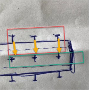
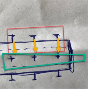
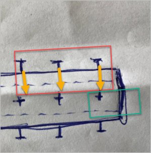
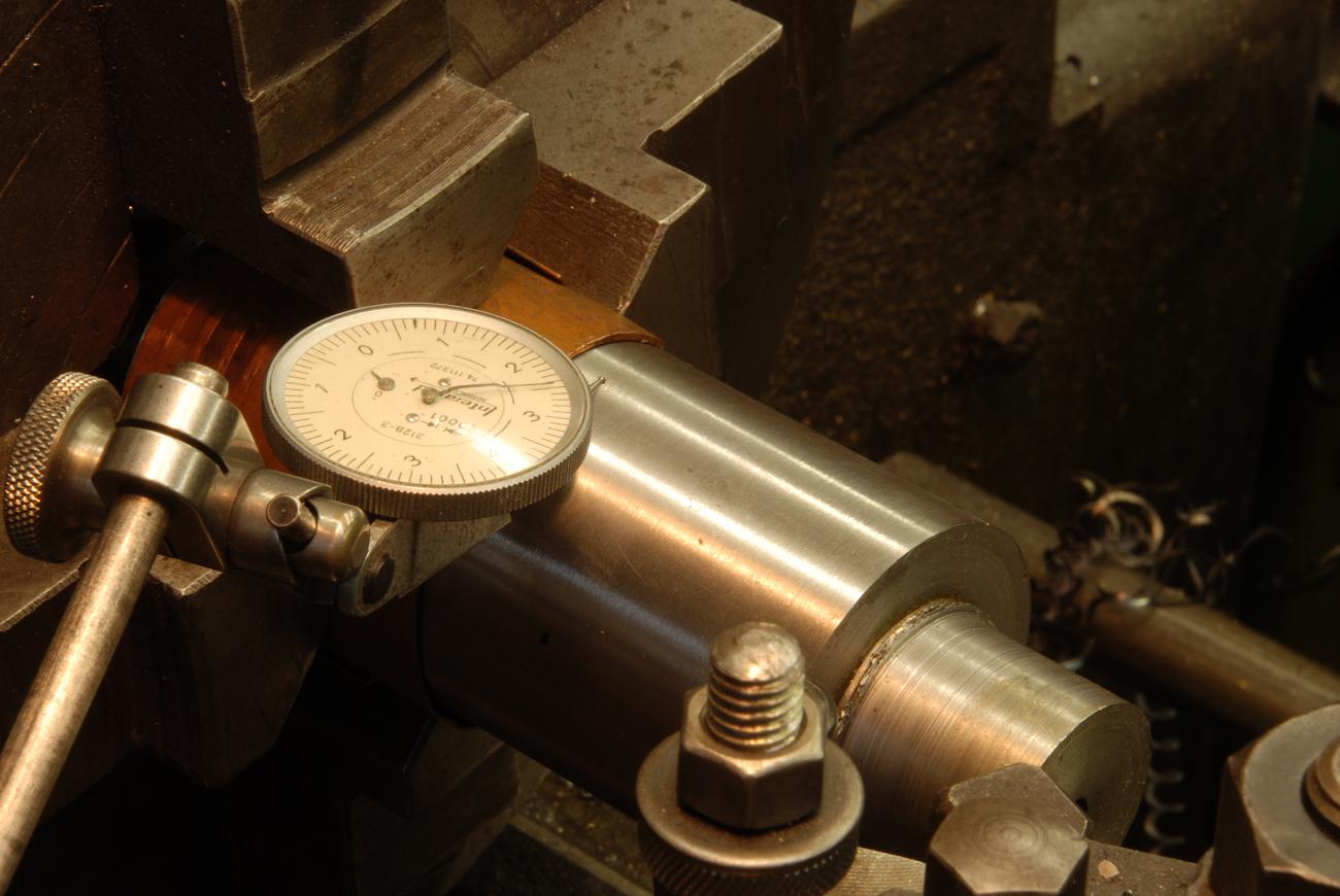
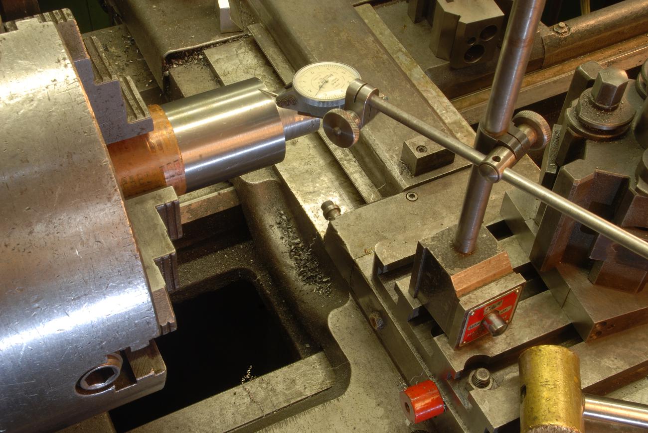
For example, take something know to be round and straight to a high degree of accuracy. Say a cylindrical square (wrap it in something obviously to not mar the surface). Use your best tenths indicator and dial it in to the best of your ability, less than a tenth and barely a flicker of needle movement. Now, roll carriage out 3 or 4 inches and indicate. I can almost guarantee it will not be as concentric as it was at chuck. Photos below show what is meant by indicating in two planes - one close to the chuck the other further out. This is a spindle housing so bores for the bearings (expensive P4s!) need to be true - and each end needs to set up and bored. The only way to ensure those bores are aligned is reference the OD and indicate it in in two planes. Its a Rohm chuck so is good quality, but its still needs tweaking to get things spot on.
There are ways to to deal with it, and its somewhat of a pita and takes some time - basically iterations of dialing it in in each plane as well as judicial tapping.
I don't agree with the idea of the spider being for alignment, they're to discourage whip afaik, but the cat head can achieve perfect alignment. The one I have and have tried to use (and its a pita) is on a watchmakers lathe. making one is simple and a great trick if you don't have 4 jaw, but with a 4 ja just being for different lengths of work and only two are used at a time - hadn't thought of that!w I'd never bother with the thing. Susquatch makes a great point on the three screws;