• Scam Alert. Members are reminded to NOT send money to buy anything. Don't buy things remote and have it shipped - go get it yourself, pay in person, and take your equipment with you. Scammers have burned people on this forum. Urgency, secrecy, excuses, selling for friend, newish members, FUD, are RED FLAGS. A video conference call is not adequate assurance. Face to face interactions are required. Please report suspicions to the forum admins. Stay Safe - anyone can get scammed.

Tread Mill Elevation Rack Repair

RobinHood

Ultra Member
Premium Member
We got a used treadmill for cheap. It had some belt tracking issues and the elevation mechanism would not work. The tracking was solved by adjusting the rollers. The elevation was a different story...

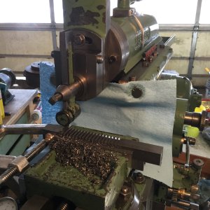
I had just recently completed the rebuild of my 1948 Peerless Shaper (it was free - just had to get it) and it was the perfect little project for it: cut a gear rack. I used my Clarkson T&C grinder to grind a HSS form tool that matched to old broken rack and away we went. I just used cold rolled rectangular stock because I do not have a good way to heat treat steel yet. So I made two racks in one go - just in case. The original seems to be hardened where the gear teeth are. I think maybe too hard and that is why it broke in the first place?

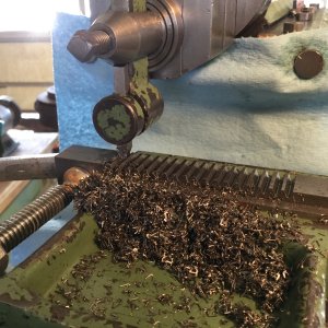
Here is the shaper cutting the racks
IMG_0185.JPG

And another shot
IMG_0186.JPG

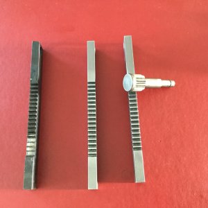
And the finished product
IMG_0187.JPG

Here you can see the heat treating of the original part on the left, also the broken teeth. The pinion is driven through a reduction gearing system that is stationary and the rack is what moves the treadmill running surface to an inclined position
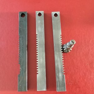
IMG_0188.JPG

Six months later, and very regular use of the treadmill, has not resulted in a failure of the incline mechanism. I guess mild steel was strong enough.
 
Cool. That turned out great. I have been machining full time for 9 years now and i have never used a shaper. I have noticed they are more popular with hobby machinists than pro machine shops. I only know of one machine shop that runs production parts on a shaper. They still use a shaper to cut a 50" long keyway inside a bore.
 
This shaper was sitting outside of a shop. It had fallen over at least once and bent the motor shaft and cross slide screw end. Someone was supposed to come get it to restore; in the end, they did not want it any more. So the guy said I can have it if I took it with me now - I did.

Not much info on the Peerless brand other than it was made in Guelph, ON. It has about a 12" stroke, and a unique variable speed drive system called a RotoCone. These are still available - I am quite surprised.
RotoCone.webp
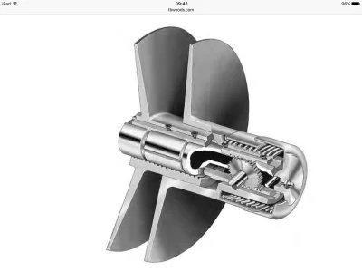
What's unique about that pulley system is that there are two racks running in key ways (180* apart) inside the shaft. These racks are geared together with a little spur gear. So if one rack moves axially one way, the other is forced to move in the opposite direction. Each half of the pulley sheath is attached to one end of one rack. There is a big spring in the shaft housing which keeps the sheaths compressed - like they are shown in the picture. The electric motor, to whose shaft this RotoCone pulley is mounted, sits on a set of rails and can be moved by an adjusting lead screw. The belt drives a pulley on the input jack shaft of the shaper. With the RotoCone in the position shown in the picture, one gets maximum speed. To slow down the shaper, move the motor away from the "stationary" pulley by "tightening the belt". As the belt tightens, it increases the pressure on the side of each sheath. Remember the spring? It can only hold the pulley sides for so long before it gives in to the pressure from the belt and the sides move further away from each other. The belt now slips deeper into the pulley - effectively reducing the diameter of it. Smaller drive pulley = slower speed. Thus you have infinitely variable speed between the fully closed, max. diameter, and the fully open, min. diameter, of the RotoCone pulley. Since always both sides of the pulley move, the belt always tracks perfectly centred (once it is aligned with the jack shaft pulley).

I thought that was quite cool.

I do apologize for coming across as a bit of a geek/nerd when it comes to mechanical systems. I just like to know how things work. That helps me understand how they should be operated and what their limitations might be.

Let me know if I bore you and I can tone it down with explanations.

Cheers, Rudy
 
Here is a cut-away of a roto-cone pulley out of the TBWOODS product catalogue

IMG_0428.webp

You can see the two racks and the spur gear between them. The top rack attaches to the LH sheath and the bottom rack attaches to the RH sheath. The spring keeps them compressed to the min distance between them, as shown. When you push with force on each sheath axially, they move apart. Imagine a v-belt on the pulley the way it is shown: the belt would engage very close to the outside circumference only = high speed. If the belt is pulled hard into the pulley, the sheaths move apart and the belt would ride much lover in the pulley = low speed.

It is a variation of a vari drive on a Bridgeport mill; or on a snow mobile. It only uses one adjustable pulley.

Hope that helps.
 
Makes sense.. although it seems excessively complex for no reason.. it may be a patent infringement avoidance thing.
My mill runs this for power feed and the spindle but it doesn't have any pinions in it, it just relies on the spring pressure to keep one set closed as far as possible and the other is adjusted via a pad and screw.
 
I do apologize for coming across as a bit of a geek/nerd when it comes to mechanical systems. I just like to know how things work. That helps me understand how they should be operated and what their limitations might be. Let me know if I bore you and I can tone it down with explanations.
Cheers, Rudy
You wont ever hear that from me! :) I'm learning lots with your project posts & explanations, Rudy.
 
The top rack attaches to the LH sheath and the bottom rack attaches to the RH sheath.
Upon closer inspection, it is the other way round: the top rack attaches to the RH sheath and the bottom to the LH one. I was in rush when i typed this up...
 
Cool. That turned out great. I have been machining full time for 9 years now and i have never used a shaper. I have noticed they are more popular with hobby machinists than pro machine shops. I only know of one machine shop that runs production parts on a shaper. They still use a shaper to cut a 50" long keyway inside a bore.

Alex what kind of machine needs a part like that? Does their shaper cut 50" in one stroke?
 
Does their shaper cut 50" in one stroke?
Yeah it does actually cut that keyway about .5 wide but it takes many strokes. Moving over and down very slowly. The parts are for natural gas fracking. I will take a closer look next time im at that shop.
 
I wasn't very clear - I meant to ask how long a stroke can that shaper make? Is it inside a bore? How do you get to 50" long? 0.5" key way seems big to me. Ships and tanks. Is that part of a compressor?
 
Ill look at the shaper closer in a couple months when i am back there. I think it was able to stroke over 50" but ill ask the old guy that uses it. The key way is internal. The parts are hydraulic components that get sent down hole before fracking begins.
 
Back
Top