Tramming KBC mill question.

whydontu

I Tried, It Broke
Premium Member
Assuming that the nod is related to an error between #217 and the frame, I'd be taking off the head and looking at the bearing surfaces. The geometry of the distance between the quill and the bearing means it wouldn't take much to generate a 0.005" nod. Might be as simple as a bit of scarf or some paint.

Image 2-5-24 at 11.18 AM.jpg
 

JustaDB

Ultra Member
Assuming that the nod is related to an error between #217 and the frame, I'd be taking off the head and looking at the bearing surfaces. The geometry of the distance between the quill and the bearing means it wouldn't take much to generate a 0.005" nod. Might be as simple as a bit of scarf or some paint.
When I assembled the mill, I made sure the mating surfaces were very clean & had just a touch of oil applied. Not saying there's nothing there, just that I would be surprised. I was pretty careful.
 

YotaBota

Mike
Premium Member
There could also be a discrepancy between #217 and the milling head itself.

Shimming the base at the front may need you to shim the sides as well to keep the rear from binding as you tighten down. But as mentioned before, shimming will be good until you swing the head to a new position. I wonder if you got the right combination of shims and then run a bead of JB Weld around the between the shims it would give enough support.

I had the X trammed to about a thou as well but the Y I never even measured. For the jobs I was doing and the knowledge I had at the time it didn't matter, I'm not in India but it was close enough.
 

JustaDB

Ultra Member
Shimming the base at the front may need you to shim the sides as well to keep the rear from binding as you tighten down
Which is why I was thinking larger, crescent-shaped shaped shims.
For the jobs I was doing and the knowledge I had at the time it didn't matter, I'm not in India but it was close enough.

I honestly don't know how much this will affect anything I make at this point, either. I just figgered I'd check it seeing as I was already there.
 

CWret

Ultra Member
Premium Member
My mill is a RF45 clone (Modern Tool’s model MD45). The 5mil nod was removed using shims.
A pair of 0.002” shims were installed above the middle bolts, 0.003” below it, and a 0.005” at the bottom.
4BD3A973-F3DE-46B1-BCDA-320F469153BF.jpeg

Shim install:
The Z gib locks were snugged so that the head would move but it took a noticeable effort. This step was considered necessary since the mill has a counter balance weight (its upward force has a rotational component that worsens the nod). The 3 head bolts were loosened and down pressure was put onto the table using the Z feed so that the 0.005” bottom shim was a tight fit and held in place by friction. The Z gib locks were tightened a little more and the 0.005” shim could still be moved. The left and right (0.002” & 0.003”) shims were installed. They were moved up and down a bit until all 5 shims had the same resistance (to being moved). The head bolts were snugged and all 5 shims became tight together. Torqued the bolts and no more nod.

(Well it wasn’t really that simple - the process needed some back and forth between balancing left-right tilt and removing nod. Also 0.003”, 0.004”, and 0.006” shims were tried before switching to above set of shims. Plus, just for sh!ts and giggles, all of the above was repeated with the counter balance disconnected.)

The bottom shim looks like Aliva’s but with shortened legs
969553BF-41E2-4AC5-B594-45BC444F83A2.jpeg
 

mickeyf

Well-Known Member
Interesting. I just got this same mill. Mine is labeled Peerless, but was originally sold by Sharp in North Vancouver. Per my research, apparently it has been sold around the world as:

Sharp VO-A1S
Kao Fong KF-VO-AIS
Husky A1S
LuxMill AM VO-A1S (UK?)
McMillan VO-A1S (Australia)
Myford VMF ?
MSC
ENCO
KBC
Craftex
Jet JVM-830
Grizzly 1004/1008

Some of the more recent variations had things like one shot oiling, which mine (1979) does not.
And someone, maybe on Practical Machinist? said "these are a copy of the Clausing 8520". What I see on lathes.uk for the Clausing is pretty similar, but not quite identical.

I have not trammed mine, just got it into the shop and in place, busy with other stuff. I have found a few examples here and there of how people managed to attach scales for DRO without too badly getting in the way of the gib locks, spindle dial, etc., but I'm going to add a power X feed first, DRO can wait.
 

CWret

Ultra Member
Premium Member
Not sure we’re talking the same mill.
Mine MD45 - from post # 30 above - where i added shims to get rid of the nod looks like this:
0FB430D5-0576-461B-B7D4-B3C3A11B33B5.jpeg
FB67C53A-B281-4D7B-8C51-84BDC7058627.jpeg
 

mickeyf

Well-Known Member
I'm referring to the one pictured in the link in post #1 - the one that started this thread. Completely different beast than the MD45.
 

CWret

Ultra Member
Premium Member
Yes
counterbalance
yes.
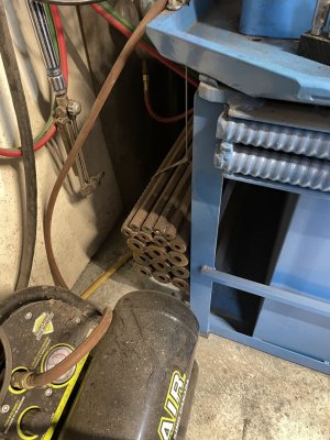
It’s 220 pounds of old rock drill steel.
Works so well that I replaced the big 9” long handle with a 6” diameter wheel (spare wheel came from the X power feed install). The wheel is not only easy with better access, but also much is faster.
 

Attachments

  • 5AABFEDE-E29F-4EBA-BBE6-9B7F9A423011.jpeg
    5AABFEDE-E29F-4EBA-BBE6-9B7F9A423011.jpeg
    548.5 KB · Views: 12

CWret

Ultra Member
Premium Member
chips on the floor
Mill is in the attached garage. It’s a big job to relocate but that’s what i plan to do. Moving it to the far corner will help keep the swarf from hitch hiking into the house. (which is also why i put an effort into keeping the floor clean)
 

Jswain

Joe
Yes

yes.
It’s 220 pounds of old rock drill steel.
Works so well that I replaced the big 9” long handle with a 6” diameter wheel (spare wheel came from the X power feed install). The wheel is not only easy with better access, but also much is faster.
Smart. Your stand looks beefy as well, I like it!
 

CWret

Ultra Member
Premium Member
Stand is 325 lb without the tool box. It has lots of rock drill steel built into it. It’s wider than the mill base so i needed the top beams (front & back) to be very HD & ridged. I measured beam deflection from the mill weight (front & back) at 0.0005”.
5631E1B9-FD55-494C-A5D3-FBBE33378E02.jpeg
PS - after doing this i got a more accurate dial test indicator (next day from Amazon) but forgot to take a pic with the better indicator)
 
Top