• Spring 2024 meetup in Calgary - tentative date Saturday, April 20/2024. Other regions are also discussing meet ups. If you want one in your area get going on organizing it! discussion
  • We are having email/registration problems again. Diagnosis is underway. New users sorry if you are having trouble getting registered. We are exploring different options to get registered. Contact the forum via another member or on facebook if you're stuck. Update -> we think it is fixed. Let us know if not.
  • Spring meet up in Ontario, April 6/2024. NEW LOCATION See Post #31 Discussion NEW LOCATION

Toolpost grinding wheel dresser

PeterT

Ultra Member
Premium Member
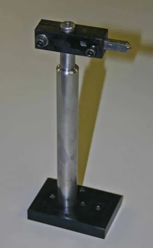
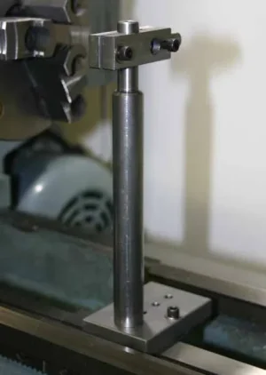
I wanted something rigid & adaptable I could set up quickly on the lathe for wheel dressing in whatever orientation the wheel diameter happened to present. Then knock it down quickly without fuss but preserve the height setting if required again. The parts are just from scrap box metal on hand.

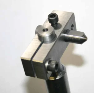
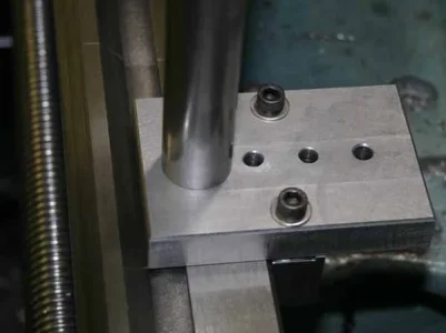
The pillar bottom surface is center relieved & tapped so it sits firmly to bottom plate with a bolt. All fasteners & set screws are 10-24. Not pretty but I'm a '1-allen key builds the whole Ikea cabinet' type guy :) The base plate has a few spaced holes so I can position the post in or out as required. Holes are c/sunk so plate lays flat on way. The head holds my standard 3/8 shank diamond dresser in 0-90-180 deg orientation. I have a few other do-dads for the head but will save for action pics.

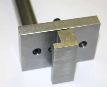
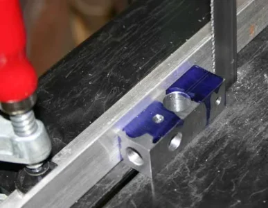
I also tried a quick & dirty band saw slitting operation instead of setting up the slitting saw arbor on the mill. It turned out fine for the intended purpose.
 

Attachments

  • IMG_5710_edited-1.jpg
    IMG_5710_edited-1.jpg
    33.8 KB · Views: 16
  • IMG_5704_edited-1.jpg
    IMG_5704_edited-1.jpg
    27.3 KB · Views: 14
  • IMG_5703_edited-1.jpg
    IMG_5703_edited-1.jpg
    32.9 KB · Views: 15
  • IMG_5699_edited-1.jpg
    IMG_5699_edited-1.jpg
    33.9 KB · Views: 14
  • IMG_5697_edited-1.jpg
    IMG_5697_edited-1.jpg
    31.5 KB · Views: 15
  • IMG_5692_edited-1.jpg
    IMG_5692_edited-1.jpg
    47.9 KB · Views: 15

PeterT

Ultra Member
Premium Member
Eventually one of these. Specifically I want to grind the cylinder liner ID & OD & maybe some other parts once I get there. I conventionally bored & then lapped a few prototype liners trying different materials & concluded that lapping is more of an ultimate finishing method. Its painfully slow. A couple thou is a mountain of material.

Right now my focus is on the crankcase & center internals. I think the cylinder assembly is pretty straight in my mind when the time comes. So I plunked around with grinder tooling which I know I'll require. I might machine some custom arbors, we'll see. I also had some grinding wheels made locally by waterjetting from a 7" dia x 0.25" wheel, I supplied the CAD file. One thing I had not counted on was sourcing wheels like this is a real bugger. It was a bit of crap shoot experiment but turned out well. Lots of wheels made once its swiss-cheesed.
 

Attachments

  • IMG_5539_edited-1.jpg
    IMG_5539_edited-1.jpg
    35.6 KB · Views: 15
  • IMG_0730_edited-1.jpg
    IMG_0730_edited-1.jpg
    42.4 KB · Views: 15

Janger

(John)
Administrator
Vendor
ah! now I follow you. Very interesting. Xyundu on you tube mounts a air powered pencil die grinder in the tool post - cheap and simple. Would that work or is it too small and bendy?
 

PeterT

Ultra Member
Premium Member
I haven't tried a pencil grinder but I could see some use for it for teeny parts. For my application I'd say small & bendy probably describes the limitations I would expect. I'm no expert but what I learned about precision grinding is:

- Grinding can be a HP gobbler. Consider a typical home shop surface grinder. It has a pretty hefty motor, yet its only taking couple thou passes across say 0.50-0.75" wide wheel on a thin contact line. Small motors will heat up pretty fast with any kind of continuous running. Even 1/3HP toolpost grinder is considered smallish.

- Precision bearings. Any kind of radial float shows up in the surface finish & dimensional accuracy which is the whole objective. But it can be much worse, if they are too sloppy you risk blowing the wheel up. Toolpost grinder bearing cartridges are typically high end, angular contact type & with heat compensation. Dremel type grinders is probably asking for trouble based on the bearings I've replaced. I've seen people use die grinders (mostly on Youtube). The work is shiny all right, but you typically don't get to see micrometer or bore gage results for some reason :)

- RPM. On small bore grinding the rpms go up as a function of required SFM. For example 1" bore could be 35-40K rpm. So this relates to bearings again, heat, lubrication & even the drive belt material (mass) because motors don't like to go that high. Air grinders I'm told are suitable & even preferred as bore goes down but they are typically very low power equivalent & gobble air.

There are some nice precision spindle motor/arbor units out there in Asian internet land favored for cnc mills that probably would work. But they are generally configured to VFD's (and usually higher 220v line voltage I noticed) & water cooled. So they get spendy pretty fast.
 

Susquatch

Ultra Member
Administrator
Moderator
Premium Member
I haven't tried a pencil grinder but I could see some use for it for teeny parts. For my application I'd say small & bendy probably describes the limitations I would expect. I'm no expert but what I learned about precision grinding is:

- Grinding can be a HP gobbler. Consider a typical home shop surface grinder. It has a pretty hefty motor, yet its only taking couple thou passes across say 0.50-0.75" wide wheel on a thin contact line. Small motors will heat up pretty fast with any kind of continuous running. Even 1/3HP toolpost grinder is considered smallish.

- Precision bearings. Any kind of radial float shows up in the surface finish & dimensional accuracy which is the whole objective. But it can be much worse, if they are too sloppy you risk blowing the wheel up. Toolpost grinder bearing cartridges are typically high end, angular contact type & with heat compensation. Dremel type grinders is probably asking for trouble based on the bearings I've replaced. I've seen people use die grinders (mostly on Youtube). The work is shiny all right, but you typically don't get to see micrometer or bore gage results for some reason :)

- RPM. On small bore grinding the rpms go up as a function of required SFM. For example 1" bore could be 35-40K rpm. So this relates to bearings again, heat, lubrication & even the drive belt material (mass) because motors don't like to go that high. Air grinders I'm told are suitable & even preferred as bore goes down but they are typically very low power equivalent & gobble air.

There are some nice precision spindle motor/arbor units out there in Asian internet land favored for cnc mills that probably would work. But they are generally configured to VFD's (and usually higher 220v line voltage I noticed) & water cooled. So they get spendy pretty fast.

Excellent summary Peter.

Time will tell if my Spindle Motor based Tool Post Grinder works or was a total waste of time and money. I'm hoping it works, but not at all confident.

Assuming it works, I also plan to adopt your approach to dressing my stones and wheels.
 

combustable herbage

Ultra Member
Premium Member
Eventually one of these. Specifically I want to grind the cylinder liner ID & OD & maybe some other parts once I get there. I conventionally bored & then lapped a few prototype liners trying different materials & concluded that lapping is more of an ultimate finishing method. Its painfully slow. A couple thou is a mountain of material.

Right now my focus is on the crankcase & center internals. I think the cylinder assembly is pretty straight in my mind when the time comes. So I plunked around with grinder tooling which I know I'll require. I might machine some custom arbors, we'll see. I also had some grinding wheels made locally by waterjetting from a 7" dia x 0.25" wheel, I supplied the CAD file. One thing I had not counted on was sourcing wheels like this is a real bugger. It was a bit of crap shoot experiment but turned out well. Lots of wheels made once its swiss-cheesed.

Hi @PeterT originally when I saw that picture I thought it was a bigger grind wheel you had used, I see that a local university is offering waterjetting service so I think I will contact them and see what the costs are and maybe do the same thing, a person could get different grits too maybe something finer and something coarser? it might make sense to do a couple because of cost of setup.

I see your other picture is that themac? if it is which model? Are you using it with a spindle straight off the motor or is it going to be a separate spindle with a belt? my intention is to get mine up and running this spring I am lucky I got 3 spindles.
I like your dresser holder too I have almost everything to make it just waiting on some slitting saw blades.
 

PeterT

Ultra Member
Premium Member
@combustable herbage yes Themac J35 internal/external. The fixed rpm, 1-direction motor drives a spindle via flat belt & swap-able pully wheels to vary surface rpm. The motor base is attached to compound via T-plate similar to a tool post setup. The spindle itself can then be raised or lowered along circular dovetails which are integrated into OD of motor can. I was apprehensive about water jetting my own wheels, like maybe micro-fracture weakening the cut edge zone, but they have been fine. Making a whole bunch of smaller wheels from a 1/4" x 8-10" surface grinder wheel is defiantly viable as a procedure, only issue is cutting cost. The grit I somewhat incorrectly chose is a bit on the fine side for what I wanted to do but it works. What I don't care for on Themacs is the odd duck spindle taper on their mandrels. I think I replicated the formula but still a PITA to make. I have a collet chuck so I can grip typical mounted points. I have done very little OD grinding.

The big thing about grinding is you need a very reliable way to infeed teeny amounts, monitor & adjust progress. The most popular way is setting compound at shallow angle & using trig to your advantage. But that feed + measure iteration approach might still be too course for precision work depending on the job. I think there are benefits to an independently mounted dial gage. I posted some pics somewhere of my last setup. I can dig them up again if you're interested.
 

combustable herbage

Ultra Member
Premium Member
For me starting out for sure I want to get the feel of it, once its all going I would like to do my 3 jaw chuck and then explore the trouble I can get into with it and build my skills but I can see the challenge you say as to feed precisely to bring something to a certain diameter a skill I still need to work on but look forward to getting there someday.
I wanted to ask you about the spindles I unscrewed the ends and had a look inside I didn't totally disassemble it everything looked ok and I believe the ends setup the preload on the bearings as it became smoother as tightened it up but it has two holes that say oil but it says the bearings are grease sealed for life so I am confused as to what oil I would put in there my thought is a small amount to splash around in there.
I also wanted to ask about the material that they use for the belts I have some access to some different habisat belting that I can make a custom size that might be an idea but on the website it looks like they are a rubber compound?
 

Susquatch

Ultra Member
Administrator
Moderator
Premium Member
The big thing about grinding is you need a very reliable way to infeed teeny amounts, monitor & adjust progress. The most popular way is setting compound at shallow angle & using trig to your advantage. But that feed + measure iteration approach might still be too course for precision work depending on the job. I think there are benefits to an independently mounted dial gage.

I had not actually considered this part of the job till you mentioned it.

But you are right. Some of the value of grinding is to improve precision a little. For me, the other side is being able to turn hard surfaces (like chuck jaws).

I think using the compound to improve the geometry of the advance will help, but only if the other adjustments are locked down. For the most part, I'm more interested in consistency than in achieving precise dimensions.

I guess all that will be explored when I have a working system.
 

PeterT

Ultra Member
Premium Member
I wanted to ask you about the spindles...
I've never had mine apart so cant offer much, but when I was eyeing used units I called Themac to discuss wat would be involved in a rebuild if the rest was otherwise OK. I believe they still offer this service but the bearings used are spendy & it doesn't take much labor before combined cost intersects a new spindle. So my own conclusion was try & buy used wisely if at all possible. I'm not saying the rebuild work cant be done, people on the forum are doing this level of work.
I unscrewed the ends and had a look inside I didn't totally disassemble it everything looked ok and I believe the ends setup the preload on the bearings as it became smoother as tightened it up but it has two holes that say oil but it says the bearings are grease sealed for life so I am confused as to what oil I would put in there my thought is a small amount to splash around in there.
Hmm.. I don't know specifics but I recall reading something similar. I seem to recall they are fussy about the oil type, the rpms can approach 40K. It could be the bearings are still greased but seal isolated from oil bath? Might be worth a call to them. They were pretty open about general information. I get the vibe that TPG's are a very niche application & generally considered old school which largely explains why they look the same today as they did 30 years ago.
I also wanted to ask about the material that they use for the belts I have some access to some different habisat belting that I can make a custom size that might be an idea but on the website it looks like they are a rubber compound?
I don't know the material but they are surprisingly thin. They told me this style is important, not just for transmitting this level of power but low mass helps mitigate issues especially at higher rpm that could affect finish. I cant say if what you are looking at would be a viable substitute. I've heard of people using different belts, but more on homebrew grinders. Maybe @RobinHood will chime in, he has done more work with his Dumore.
 

PeterT

Ultra Member
Premium Member
I think using the compound to improve the geometry of the advance will help, but only if the other adjustments are locked down. For the most part, I'm more interested in consistency than in achieving precise dimensions.
The cross slide has to be locked or else you can toss any hope of accuracy & consistency out the window, at least that's been my experience. Many typical TPG jobs requires the lathe to be traversing under power feed, so the carriage has to move of course. What I find with TPG, especially sitting on top of the compound - even though the motor rotor is balanced & wheel is dressed & low arbor runout... all that stuff, the lathe sliding ways & moving surfaces get kind of lively with the vibration buzz. This was evidenced by my 10's indicator measuring cross slide feed. TPG motor off = rock steady needle. TPG motor on = needle oscillation. A compound mount is yet another layer or potential movement that could be reduced, maybe by solid toolpost. But then you give up ability to infeed at shallow angle, so choose your tradeoff.

I said this before but my initial high hopes for TPG has been tempered quite a bit. It will still be a great tool for many applications. But for many others its kind of a uphill battle. Its virtually impossible to have TS support without TPG being in the way so that's a big bummer. You can cut hard materials & you can make things shiny for sure. Precision is one of those 'it depends' things.
 

PeterT

Ultra Member
Premium Member
For me, the other side is being able to turn hard surfaces (like chuck jaws).
Before you go too far down that path, do some Googling on the pros & cons of that procedure. I'm not talking about the standard stuff like ID grinding or jaw pre-loading etc.
I came away with an impression that a bad chuck could be 'improved', but it could never attain what a new/good chuck could offer due to the geometry. ie. chuck jaws are ground flat on a surface grinder & grip all diameters on their tangent point center vs something different for jaws ground rotationally. I started to draw this out in CAD just out of interest but kind of got sidetracked, I do see what they are talking about though. Maybe worthy of another post. Its about as controversial as lathe bed twist.
 

RobinHood

Ultra Member
Premium Member
I did get a new endless flat belt through Transmission Supply for my Dumore #44. It works very well and runs smoothly.

TPGs are low mass, compact grinders. They are not like a “proper“ cylindrical grinder or a surface grinder which usually have lots of heavy cast iron on them to dampen out vibrations. TPGs also typically run at higher spindle speeds (because of the wheel size) and thus are more prone to vibrations or “buzz” as @PeterT points out. This will affect the surface finish.

As far as accurately grinding to specifications using a TPG: it is possible, but tricky. You really need to know your lathe well. A lathe usually has relatively small dials compared to a purpose built cylindrical/surface grinder. This makes setting DoC more challenging. An accurate DRO/DI helps. I found that setting dials while the TPG is not running does not work well. Locking axis can help. But to my surprise, I found that leaving all the lathe axis “floating” produced the best results (TPG is always running if it can be safely done so after initial set-up). This emulates what happens on cylindrical/surface grinders - none of the axis are usually locked during grinding. Also, if you have room, set the dials with the grinding wheel well away from the work piece and let the axis “settle” with long lead-in/lead-out distances.

Yup, tail stock support can be a problem as well. Creative set-ups are then required. I’ve had to angle the TPG spindle axis at up to 30*-45* off of parallel to the Z-axis to achieve clearance. Then dress the wheel parallel to the lathe’s Z-axis. A bit of a waste of grinding wheel, but cest la vie…
 

Susquatch

Ultra Member
Administrator
Moderator
Premium Member
Before you go too far down that path, do some Googling on the pros & cons of that procedure. I'm not talking about the standard stuff like ID grinding or jaw pre-loading etc.
I came away with an impression that a bad chuck could be 'improved', but it could never attain what a new/good chuck could offer due to the geometry. ie. chuck jaws are ground flat on a surface grinder & grip all diameters on their tangent point center vs something different for jaws ground rotationally. I started to draw this out in CAD just out of interest but kind of got sidetracked, I do see what they are talking about though. Maybe worthy of another post. Its about as controversial as lathe bed twist.

I believe I understand. But maybe not.

When I first started down this path, I realized that my 3 jaw did not have flat jaws. They are slightly concave. I know that from the bite marks they leave in soft work.

Therefore, I deliberately set out to measure their radius to see if it could be duplicated with a grinder. Sure enough it is just slightly smaller than the spindle and chuck bore size. So that can be copied just by grinding them when they are in that position. I have already made an expansion collar to put pressure on the Jaws during grinding and it is sized to do so at that position.

I'll refrain from commenting on the other rabbit hole issues till they come up.

In the meantime, I did some base line measurements of my chuck.

I posted the numbers on my own thread 'Tool Post Grinder' https://canadianhobbymetalworkers.com/threads/tool-post-grinder.4327/post-73539
 

PeterT

Ultra Member
Premium Member
Yeah, like I say I'm not well versed on the issue. I've been meaning to look at my jaws up close & personal because I could have sworn they have a slight concave profile viewed from the front, but not sure on equivalent radii (att stock photo).

Re 'expansion' collar, I think you want to have them preloaded to simulate clamping force pre-re-grinding, no? I've seen inter-jaw wedges used & other tricks.
 

Attachments

  • SNAG-2022-04-14 6.20.20 PM.jpg
    SNAG-2022-04-14 6.20.20 PM.jpg
    19.2 KB · Views: 3

Susquatch

Ultra Member
Administrator
Moderator
Premium Member
Re 'expansion' collar, I think you want to have them preloaded to simulate clamping force pre-re-grinding, no? I've seen inter-jaw wedges used & other tricks.

Yes, exactly.

Here is a photo of my fixture. It's a poor man's device made out of an old 4 inch socket. It already had the perfect OD as discussed before so I simply left it as is. The outside jaw screws are removed and replaced with longer ones and sleeves so they can be tightened properly and the Jaws think they are holding some work. If you look closely, you can see the concavity of the jaw teeth.

20220414_204042.jpg 20220414_203951.jpg
 
Top