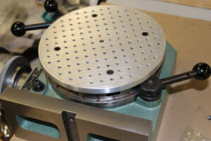
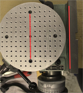
I've been meaning to make this for some time. Now I need it, so time is up. My RT platten is 6" so I made it a bit bigger at 7". I was thinking I could go bigger yet & get added utility on my lathe face plate, but I start to run into other obstacles on the RT so call it good at 7" & see how this turns out first. Mostly my intended projects are small so I came up with a 0.5" grid of 8-32 tapped holes, retained with four 1/4-20 hold down bolts.
You are using an out of date browser. It may not display this or other websites correctly.
You should upgrade or use an alternative browser.
You should upgrade or use an alternative browser.
Tooling Plate for Rotary Table
- Thread starter PeterT
- Start date
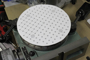
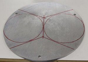
I have some nice surface ground, cast aluminum off cuts. Its within .001" thickness & very flat. No other prep is required. This slab is 3/8" thick so I tapped straight through so leaves possibility to use the other side one day. Only downside is aluminum is a bit ding-able & threads aren't as strong as if it were CI or non distorting steel. Another reason for 7" is I can just squeak in another disc of same size. Why... I'm not really sure, but keep my option open.
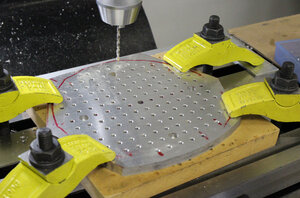
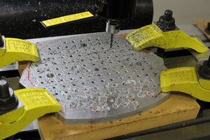
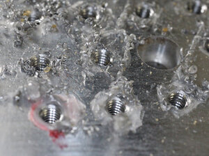
After about 3" into the bandsaw cut by blade let go. Not broke but parted company with the wheel. More on that later. 4 hours later of futzing & adjusting & looking for the second blade I KNEW I bought but apparently stored in a secret hiding place... finally resumed work. I roughed it out, clamped with MDF underneath, spotted, drilled, tapped many, many holes. 42 bottles of beer on the wall, 42 bottles.... To break up the monotony I tried different cutting fluids. This cast AL is funky stuff. It likes to plug even sharp, chip ejecting taps. The winner IMO was was this LPS tapping cream. Yes, I do have a tapping head.
After about 3" into the bandsaw cut by blade let go. Not broke but parted company with the wheel. More on that later. 4 hours later of futzing & adjusting & looking for the second blade I KNEW I bought but apparently stored in a secret hiding place... finally resumed work. I roughed it out, clamped with MDF underneath, spotted, drilled, tapped many, many holes. 42 bottles of beer on the wall, 42 bottles.... To break up the monotony I tried different cutting fluids. This cast AL is funky stuff. It likes to plug even sharp, chip ejecting taps. The winner IMO was was this LPS tapping cream. Yes, I do have a tapping head.
Attachments
Last edited:
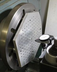
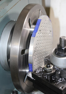
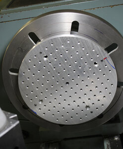
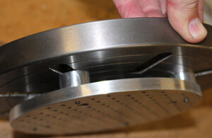
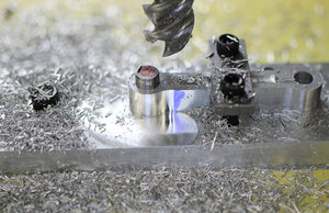
One it was tapped with no boo-boos (YAY!) I made some equal length standoffs for my face plate, zeroed on the reamed center hole and then proceeded to generate lots of sharp aluminum projectiles making the disc round. I kind of forgot about this operation from another project. Its worth taking the time to cut as much excess as you can away with bandsaw & not leaving ears that have to be trimmed down as much. The reason is interrupted cuts need to be relatively shallow or it risk pushing the part off center. Aluminum isn't too bad, steel or iron would be worse & also more of a potential balance issue.
Anyways, it got done. Janger we need to talk LOL.
Anyways, it got done. Janger we need to talk LOL.
Attachments
Very nicely done Peter.
I have bolted parts the the rotary table and used the mill to cut off the excess material to make a disc. Saves the lathe from the interrupted cuts & and less chance of the part moving wrt the center location since there can be less tool pressure in a milling operation.
That of course only works if the part is allowed to have fixturing holes in it - as is the case with your Tooling Plate.
Thanks all.
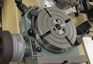
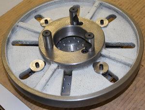
Brent, the lathe face plate is D1-4. I have one that came with the lathe that is a bit bigger & slightly different slot layout. The one shown in pic I got off ebay several years ago but what I hadn't realized at the time is it was a store front for Precision Mathews aka Quality Machine tools. I had to work at it a bit to fit the nose spindle, it was quite tight. Now fits nice & snug. I took a light facing cut off once that was established & it seems to run true. One of the ideas I had at the time was to simply drill an array of tapped holes in the CI lathe faceplate itself, similar to the tooling plate. Still an option but there is actually quite a bit of lost area with the slots & center hole & there & thicker webs on the back side which would have to be blind tapped holes.
Rudy, yes I was going to rough mill off the excess material in RT before lathe, or maybe even leave it at that if finish was OK. I needed the 8-32 based standoffs & washers for another project so just went ahead with the lathe & lived with interrupted cutting. If it was steel or CI, for sure I would use the RT method. I've seen people use these special lathe cutting tools that are meant for front face parting/grooving, kin dof like an annulur cutter tooth. But they are either custom tools or special purpose, neither of which I have. RT milling is the best method.
Ouch. That one hit way too close to home.4 hours later..... looking for the second blade I KNEW I bought but apparently stored in a secret hiding place...
I've seen people use these special lathe cutting tools that are meant for front face parting/grooving, kin dof like an annulur cutter tooth
I believe that operation is called “ trepanning”; it does require special geometry tooling. I have ground some HSS for just this purpose. Once I got the tool angles correct, it worked very well. Buying inserted trepanning tooling is quite expensive, and for the few times one would use them, probably not worth it.
You are probably thinking CNC when you say “Janger we need to talk LOL.”? I know the feeling when you have to do dozens of repeated work steps....
Anyway you got it done and it looks perfect.
One thing I realized - for some odd reason the T-slots on my RT are not at polar alignment. When my table reads zero on the graduation, the slots are at 30-deg angle. I have never figured out why but that's what it is. When I drilled & tapped my plate it was done on mill table to typical XY coordinates on 0.5" center. I am pretty sure I can make a little false indicator arm to temporarily replace the one on it now which will point to zero on the table. I don't want to mentally add 30-deg to actual angle what I'm working on.
First I thought a better solution would have been like following, however there is no guarantee the RT hold-down holes would nest properly in the array grid of threaded holes. Also if your RT has 3 or 6 slots vs 4, this would present a similar issue. Hopefully I haven't confused everyone.
Alternate?
- drill the hold-down counterbore holes in the slab
- mount the slab to RT using bolts
- zero the RT table
- drill tap the array of holes
- mill off the excess material
@PeterT , I suspect the slots are off the 30 degrees so that you can clamp something down and work on it with the table at zero and thus the clamp will not be in the way....if that makes sense? Mine has 6 slots but I am not able to confirm if they are offset from 0 degrees
I think you are onto something here, Brent.
Just checked the 12” BP RT: it has 4 slots, one is aligned with ”0”; the adjustable pointer is in that location. There is an alternate reference line at 45* off of the primary (adjustable) reference - works well if clamps are in the way.
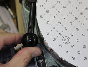
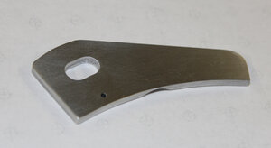
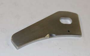
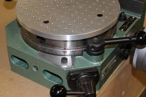
I made a 30-deg compensated arm for my RT. After some trial & error I basically just glued the paper pattern onto some scrap 1/8" aluminum. There were a few extra chamfers & notch on the underside to allow for some casting features, but it serves the purpose. You can see the stock one & what I was trying to accomplish.
Attachments
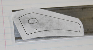
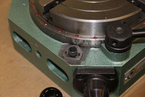
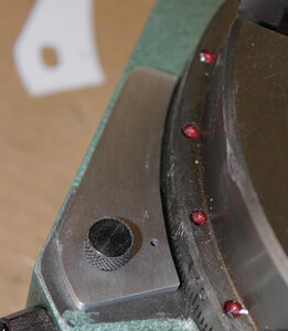
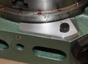
I gave myself a bit of wiggle room on the curved slot where the retention screw holds it down. But with the tooling plate attached & compensated sector arm set to zero the grid is parallel & perpendicular to the RT datum as best I can tell. So 30-deg must have been their design offset angle.
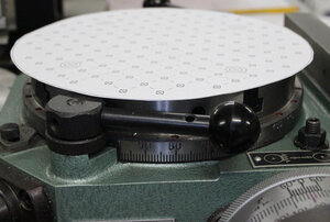
Once I had it mounted I kind of remembered a bunch of applications where the part just positions where it positions, no choice in the matter. Then you have to make an angle cross reference table to equivalent degrees like add 180 or subtract 90, or whatever it takes. So the extended arm is maybe just a convenience gadget I'll probably only use for the tooling plate. I drilled a small hole to indicate the normal zero so I can be lazy & leave it on
Once I had it mounted I kind of remembered a bunch of applications where the part just positions where it positions, no choice in the matter. Then you have to make an angle cross reference table to equivalent degrees like add 180 or subtract 90, or whatever it takes. So the extended arm is maybe just a convenience gadget I'll probably only use for the tooling plate. I drilled a small hole to indicate the normal zero so I can be lazy & leave it on
Attachments
Last edited:
Example use. I have a fixture plate pre-drilled to any convenient 0.5" tooling hole spacing. Fixture locates the radial engine link rod by dummy wrist pin & a stop pin (on the other side) & secured with simple strap clamp. Then I can mill the dog bone round-over profile. I put tape over the plate so I don't have shrapnel embedding into the tapped holes.
Attachments
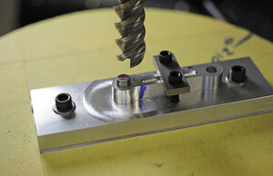
Its carbide, uncoated, 45-deg helix? Usually intended for aluminum which is what I use it for. Its razor sharp & makes a real nice finish. I got it from Travers a few years back when they had a high % discount sale. Normally I avoid them because they are spendy. After trying it out I went back to get some smaller diameters & didn't see that particular brand so maybe they were blowing them out. There are +/- similar ones though, they are quite common.
I just ordered some similar ones from Ali but in smaller metric sizes. Should be arriving soon. I'll let you know how they work.
I just ordered some similar ones from Ali but in smaller metric sizes. Should be arriving soon. I'll let you know how they work.