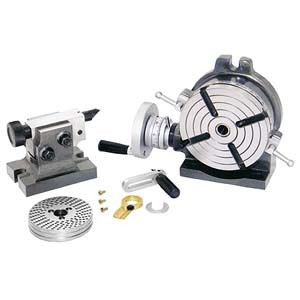
So, I acquired a 6" HV RT which is basically this one sans TS and dividing plates.
 www.busybeetools.com
Then I order a dividing plate kit from Amazon https://www.amazon.ca/gp/product/B01N249BVJ/ref=ppx_yo_dt_b_asin_title_o07_s00?ie=UTF8&psc=1
These are the fails.....

With the crank handle removed the plate should simply mount on this back plate which it does. Note the groove on the shaft. That groove needs to be exposed with the plate and sector arm installed in order to accept the sector arm retaining spring.
The first thing discovered is that the crank handle assembly is way too long with a plate installed and the spring in the plunger assy is brutally strong
Next thing discovered was that with the sector arm installed, the groove for the sector arm retaining spring wasn't exposed
The third thing discovered was that the sector arm wouldn't allow the crank handle plunger pin to engage the plate holes on the two inner hole patterns
And lastly the shaft where the crank handle mounts extends past the crank so you can't retain it with the washer and screw that came with the RT
Will present my fixes in another post, but this is how it came together out of the box.... Not Happy.
@140mower , @David_R8 Have you tried mounting your dividing plates yet?
ROTARY TABLE 6IN. C/W TAIL STOCK/INDEXING B2485
Busy Bee Tools is Canada's largest Woodworking & Metalworking retailer. Find power tools, woodworking tools & metalworking tools at factory direct prices.
www.busybeetools.com
Then I order a dividing plate kit from Amazon https://www.amazon.ca/gp/product/B01N249BVJ/ref=ppx_yo_dt_b_asin_title_o07_s00?ie=UTF8&psc=1
These are the fails.....

With the crank handle removed the plate should simply mount on this back plate which it does. Note the groove on the shaft. That groove needs to be exposed with the plate and sector arm installed in order to accept the sector arm retaining spring.

The first thing discovered is that the crank handle assembly is way too long with a plate installed and the spring in the plunger assy is brutally strong

Next thing discovered was that with the sector arm installed, the groove for the sector arm retaining spring wasn't exposed

The third thing discovered was that the sector arm wouldn't allow the crank handle plunger pin to engage the plate holes on the two inner hole patterns

And lastly the shaft where the crank handle mounts extends past the crank so you can't retain it with the washer and screw that came with the RT
Will present my fixes in another post, but this is how it came together out of the box.... Not Happy.
@140mower , @David_R8 Have you tried mounting your dividing plates yet?
Last edited:

