The oldest Chipmaster in captivity
It may be an extravagant claim, it is number 1006, the sixth Chipmaster, made in 1956 according to the label on the tailstock end of the bed. (Photo 2). A few years after this was made I was a first year apprentice draughtsman at the Marconi Wireless Telegraph Company in Chelmsford, Essex. For the first year I went to Colchester technical college full time to be taught City and Guilds Machine shop engineering: doing a three year course in one year and ordinary national certificate. I did not then appreciate how lucky I was.
We used to spend all Friday in the machine shop where, among the many machine tools were two brand new Chipmasters. There was a scramble amongst about ten students to get on them first. Then they were new, shiny, and ran like the smoothest machine in the shop. We even had a tour around the Colchester lathe factory in Colchester; I particularly remember the foundry, black sand everywhere and very hot.
When I retired I looked at a few Chipmasters, but the real problem was how to get it delivered. I found only one local company who could deal with machine weighing about a ton. They gave me a price, which was more than I thought I was going to pay for a reasonable lathe, to collect and deliver such a machine. When I questioned the price he said it was simply the cost for a driver and truck for a day’s work. It did not matter at all to him what the machine would cost. He then said what machine did I want as he had a contract to clear some machines from Teddington University.
When I said a Colchester Chipmaster; he thought they might have one of those so to call him back in a couple of weeks. So I called him and arranged to see it at his yard. It looked pretty shabby with only a three jaw chuck. However, I agreed his asking price if he would deliver it about 5 miles away and (a big and) manhandle it to my shed which was over about 50 feet of uneven lawn. With a grimace he agreed. Well four big chaps arrived in a Hiace truck and using their considerable strength manhandled it to the concrete surface of my shed. I thanked them and gave what I thought was a good tip for this.
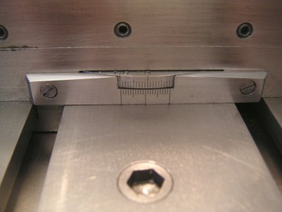
So there it was, shabby and to my dismay, when I checked it over with a test bar etc. with a fairly worn bed. I even made several graphs of the wear at one inch intervals along the bed in the vertical and horizontal using a clock gauge along a test bar. The rest of the machine was in relatively good order. I think it may have had a relatively light use, doing simple repeated tasks with little use of the feed or screwcutting facilities etc. Well here it was and it was not easily going to go anywhere else worn bed or not. The wear on the inverted vee (about 0.005” max,) was mainly at the areas close to the chuck.
The tailstock sliding and guiding surfaces were in much better condition even untouched closer to the chuck end. So I hatched a plan to simply remove the areas, which were higher than the lowest point to make the saddle guide surfaces flat and straight again. I dismantled the tailstock and used the lower base as a guide to mount a clock gauge on. This slide base was moving on much less worn areas than the saddle moved on, so this was my “reference straight edge”. Not perfect but after some correction, better than anything else I had.
I sharpened up my scraper and got absolutely nowhere, just skidding across the “hardened surfaces” Not all early Chipmasters had hardened beds it was then a customer option with no indication if it was hardened or not. Now what? I made some home made files by gluing cut up sections of a linishing belt to various pieces of wood. These were my files to finally make or completely destroy the lathe bed. It seemed terribly cruel to vandalise virtually unworn pristine surfaces with a sanding pad, but bit by bit the clock gauge was reading less and less. As I progressed I used finer grit grades. I settled for readings that while not to Schlesinger standards were pretty good even though I say it myself. I did not do anything with the leadscrew or feed shaft to suit this slightly lower saddle, it seemed quite good as it was.
The tailstock also had what I think is normal wear at the front of the base plate. The barrel pointed downwards about 0.008”. I shimmed it up to be parallel with the bed in the vertical plane. It was OK in the horizontal plane. The result was that the barrel axis was now about 0.006” too low. The barrel has a No 3 Morse taper, now nearly all my tailstock fittings from my previous lathe are No 2 Morse.
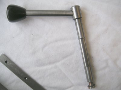
I made a No 3 Morse male sleeve with a No 2 Morse bore which is eccentric to the outer Morse taper by about 0.015”. This was fitted and pulled into position by a long hollow screw in the barrel bore. Before it was pulled tightly into the barrel it was rotated to match the height of the spindle. Horizontal adjustment was made in the normal manner using the set over adjustment on the tailstock base. The result is a preferred No 2 Morse and on centre and parallel in both axes. I also adapted the tailstock to take the capstan feed I had made for my previous Denham lathe. This now permits nearly five inches of travel.
A good clean up and paint, I matched the original dark green paint, and careful reassembly seemed to wash away those shabby years. The spindle bearings seemed to be as good as new which was a relief; it would have been a big problem otherwise. I never intended to keep the massive 5hp motor or the variator speed control fitted as standard. These were removed & replaced with a Telecamique inverter and a new 1.5hp three phase motor. I cut a hole in the lower stand where the original speed control was located to fit the inverter. The existing rear mounted switch box internals were modified so that it could switch the inverter for forward, off and reverse. A variable resistor is housed inside the on/off knob so that rotating the knob increases or decreases the speed. This made for a neat clean operation with the wiring inside the existing, hollow on/off/reverse lever. (Photo 1)
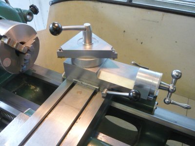
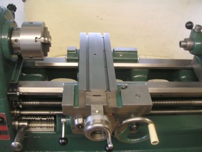
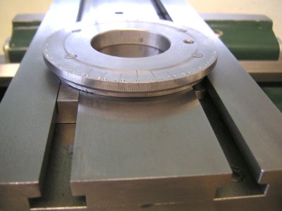
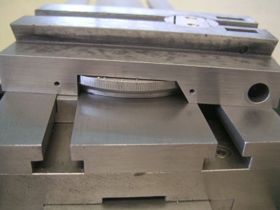
The cross slide was modified by adding tee slots for greater versatility and to mount my lever locking topslide in place of the original topslide. The advantage of this is that it can be moved and locked anywhere at any angle on the cross slide,(Photo 5). The cross slide feedscrew was worn in the middle part. It is a two start thread of 0.200” lead or 5 TPI twice. I set this up in the lathe, which now had no feed screw. I fixed a stop at the end of the cross slide and manually pushed the slide up to the stop on re-cutting the feedscrew and manually withdrew it to return the cutting tool to make another cut.
With the lathe set at 5 TPI, I found that I could make one cut with the screwcutting dial at number one then a second cut at number three. This is when the screw cutting dial has rotated 180 degrees from number one. The purpose of this was to make the second cut along the other screw thread on a two start thread. Using the topslide set parallel to the lathe axis to advance and retract the cut. I cut off just enough so that the worn part was the same as the rest of the screw. Albeit with a thinner thread part and a wider groove between the screw flanks. The reasonably worn nut was cut up to make it adjustable.
I was most pleased with the result; it is about 2 to 3 thou backlash over the entire travel of the cross slide. The end result of my butchery to the lathe bed was that when I was making the vertical column for the Stepperhead lathe I was able to turn a 450mm long, 75mm dia Mild steel bar for the full length to within about 0.0005” and nobody was more pleased and relieved than me.
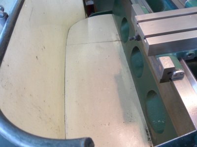
The standard splash guard on a Chipmaster is a deep affair reaching down nearly to the floor. Where a suds pump is normally located but was missing in my case. This was not a problem for me, as brush application suffices. If you dropped a tool or part, it became a real pain to retrieve it from deep down among the swarf. At the point where the lathe bed sits on its substantial base support is a gap about 5mm wide. I cut a sheet of 6mm plywood to fit the space between the bed and the splash guard with about 15mm angle aluminium fitted to the splash guard to support the other side using self tapping screws. The edge of the plywood was tapered to fit into the gap and rest on the angle support, (Photo 5). The result works very well as anything dropped down can be reached and swarf is easily accessed for cleaning.
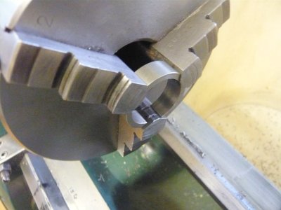
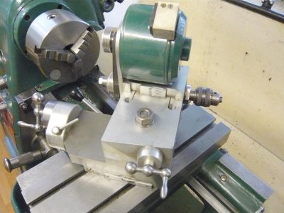
I cleaned up the existing three jaw chuck and reground the jaws using a Dremmel. Along time ago I cut a ring of steel into three equal parallel ended segments. These can be positioned between the chamfered faces of the jaws, tightening the jaws with these in place pushes the jaws in a similar manner to the normal operating mode and allows clear access for grinding the jaw contact faces (Photo 14). Ebay supplied a four jaw chuck and a Jacobs Rubber flex chuck but I had to make the chuck holder to fit the lathe.
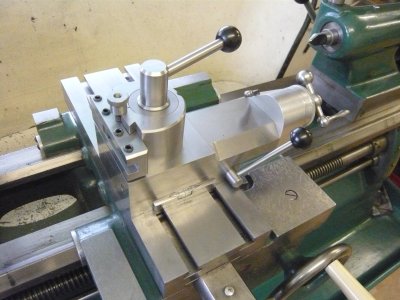
I have since made a new Lever Locking Topslide, (Photo 8). This features an oval gib of my own design. It enables the whole upper slide to be solidly locked to its base unit for the full slide length.
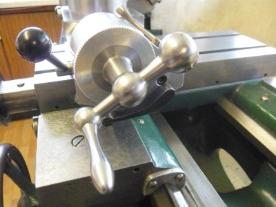
A locking lever is positioned just below the feed dial to do this, (Photo 10). It has a screwcutting withdrawal lever for external/internal screwcutting, the intermediate spindle runs on ball bearings and the long feedscrew nut is machined, not moulded from acetal, and this can be adjusted for backlash on the feedscrew.
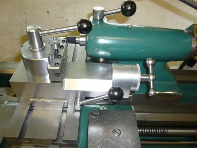
It has a choice of toolholders, the triangular one for tipped inserts can be inverted and then mounted on the far side of the item being turned like a rear parting tool, (Photo 11). This is very useful if there is a lot of metal to be removed on a long part, it avoids nearly all the swarf being thrown forwards and seems to assist in getting a good surface finish.
Being able to place the topslide on the far side of the piece being turned is also very useful for screwcutting up to a shoulder or a blind bore. The topslide is set at an angle to suit the thread, say 60 degrees to the lathe centreline. Then the cutting tool is positioned just slightly away from the shoulder with the saddle up against a bed stop. To cut a righthand thread the lathe is run in reverse and when the leadscrew is engaged the cutting tool will move away from the chuck to cut the screwthread. This enables the cut to be applied while the lathe is rotating to form a thread depth undercut and avoids scary moments trying to disengage the leadscrew before the tool hits a shoulder as in the normal method.
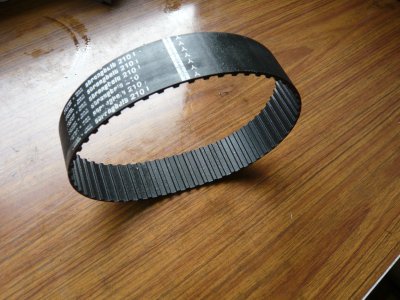
One main feature of a Chipmaster is the toothed belt drive to the mandrel. As good as it is, it still makes a whine due, I guess, to air being forced out of the tooth recesses during rotation. I worked out that I could just about fit a polyvee belt in place instead. Two aluminium sleeves grooved for a wide polyvee belt are pressed onto the existing toothed pulleys. I was going to Loctite them on but it was not necessary. I was lucky my calculations were good, as the belt tension is just right, lucky because there is no space for a jockey pulley anyway, (Photo 6). This new polyvee drive is great; the lathe is like a new machine, so much quieter than before. To be fair, polyvee belts did not exist in 1956 so the toothed belt was the latest technology then (Photo 7).
To finally finish it off I made a set of bed wipers for the saddle. The holes were already drilled and tapped but the original ones were not fitted, I suppose this had to be specified when it was first ordered.
Another nice feature of a Chipmaster is the power feed disengagement up to a bed stop, very useful for boring etc. All in all, it is a great machine, probably a bit under powered, should have got a 2 hp motor instead of 1.5 hp but it is not a problem for most of the things I do and back gear can always be engaged for large diameters etc.
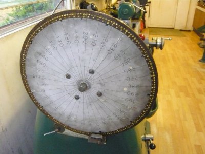
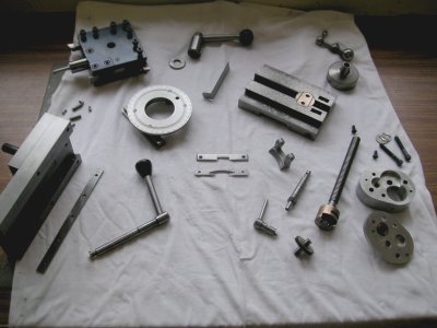
Over time I have added many attachments, a topslide milling/drilling spindle., (Photo 15). A large brass disc scale from an old rusty meat scale has 200 and 180 holes around the periphery. This can be mounted on the outside end of the spindle for indexing, (Photo 16) I have also made a rotary table that can be mounted on the cross slide in the vertical or horizontal. A Harrison vertical slide has also been adapted to fit the cross slide.
It is 60 years old now and is still going strong; it still runs as smoothly as the ones I used at college as an apprentice. It has weathered time very well; I only wish I could say the same thing about its owner!
Photo 1 All cleaned up

It may be an extravagant claim, it is number 1006, the sixth Chipmaster, made in 1956 according to the label on the tailstock end of the bed. (Photo 2). A few years after this was made I was a first year apprentice draughtsman at the Marconi Wireless Telegraph Company in Chelmsford, Essex. For the first year I went to Colchester technical college full time to be taught City and Guilds Machine shop engineering: doing a three year course in one year and ordinary national certificate. I did not then appreciate how lucky I was.
We used to spend all Friday in the machine shop where, among the many machine tools were two brand new Chipmasters. There was a scramble amongst about ten students to get on them first. Then they were new, shiny, and ran like the smoothest machine in the shop. We even had a tour around the Colchester lathe factory in Colchester; I particularly remember the foundry, black sand everywhere and very hot.
When I retired I looked at a few Chipmasters, but the real problem was how to get it delivered. I found only one local company who could deal with machine weighing about a ton. They gave me a price, which was more than I thought I was going to pay for a reasonable lathe, to collect and deliver such a machine. When I questioned the price he said it was simply the cost for a driver and truck for a day’s work. It did not matter at all to him what the machine would cost. He then said what machine did I want as he had a contract to clear some machines from Teddington University.
When I said a Colchester Chipmaster; he thought they might have one of those so to call him back in a couple of weeks. So I called him and arranged to see it at his yard. It looked pretty shabby with only a three jaw chuck. However, I agreed his asking price if he would deliver it about 5 miles away and (a big and) manhandle it to my shed which was over about 50 feet of uneven lawn. With a grimace he agreed. Well four big chaps arrived in a Hiace truck and using their considerable strength manhandled it to the concrete surface of my shed. I thanked them and gave what I thought was a good tip for this.
So there it was, shabby and to my dismay, when I checked it over with a test bar etc. with a fairly worn bed. I even made several graphs of the wear at one inch intervals along the bed in the vertical and horizontal using a clock gauge along a test bar. The rest of the machine was in relatively good order. I think it may have had a relatively light use, doing simple repeated tasks with little use of the feed or screwcutting facilities etc. Well here it was and it was not easily going to go anywhere else worn bed or not. The wear on the inverted vee (about 0.005” max,) was mainly at the areas close to the chuck.
The tailstock sliding and guiding surfaces were in much better condition even untouched closer to the chuck end. So I hatched a plan to simply remove the areas, which were higher than the lowest point to make the saddle guide surfaces flat and straight again. I dismantled the tailstock and used the lower base as a guide to mount a clock gauge on. This slide base was moving on much less worn areas than the saddle moved on, so this was my “reference straight edge”. Not perfect but after some correction, better than anything else I had.
I sharpened up my scraper and got absolutely nowhere, just skidding across the “hardened surfaces” Not all early Chipmasters had hardened beds it was then a customer option with no indication if it was hardened or not. Now what? I made some home made files by gluing cut up sections of a linishing belt to various pieces of wood. These were my files to finally make or completely destroy the lathe bed. It seemed terribly cruel to vandalise virtually unworn pristine surfaces with a sanding pad, but bit by bit the clock gauge was reading less and less. As I progressed I used finer grit grades. I settled for readings that while not to Schlesinger standards were pretty good even though I say it myself. I did not do anything with the leadscrew or feed shaft to suit this slightly lower saddle, it seemed quite good as it was.
The tailstock also had what I think is normal wear at the front of the base plate. The barrel pointed downwards about 0.008”. I shimmed it up to be parallel with the bed in the vertical plane. It was OK in the horizontal plane. The result was that the barrel axis was now about 0.006” too low. The barrel has a No 3 Morse taper, now nearly all my tailstock fittings from my previous lathe are No 2 Morse.
I made a No 3 Morse male sleeve with a No 2 Morse bore which is eccentric to the outer Morse taper by about 0.015”. This was fitted and pulled into position by a long hollow screw in the barrel bore. Before it was pulled tightly into the barrel it was rotated to match the height of the spindle. Horizontal adjustment was made in the normal manner using the set over adjustment on the tailstock base. The result is a preferred No 2 Morse and on centre and parallel in both axes. I also adapted the tailstock to take the capstan feed I had made for my previous Denham lathe. This now permits nearly five inches of travel.
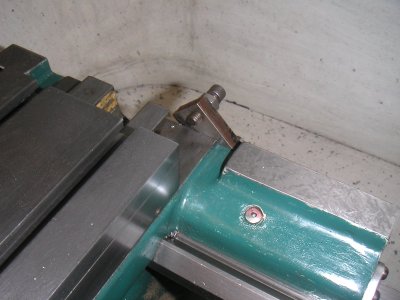
A good clean up and paint, I matched the original dark green paint, and careful reassembly seemed to wash away those shabby years. The spindle bearings seemed to be as good as new which was a relief; it would have been a big problem otherwise. I never intended to keep the massive 5hp motor or the variator speed control fitted as standard. These were removed & replaced with a Telecamique inverter and a new 1.5hp three phase motor. I cut a hole in the lower stand where the original speed control was located to fit the inverter. The existing rear mounted switch box internals were modified so that it could switch the inverter for forward, off and reverse. A variable resistor is housed inside the on/off knob so that rotating the knob increases or decreases the speed. This made for a neat clean operation with the wiring inside the existing, hollow on/off/reverse lever. (Photo 1)
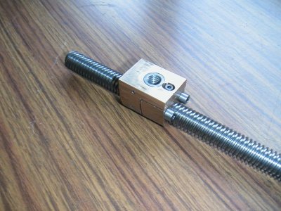
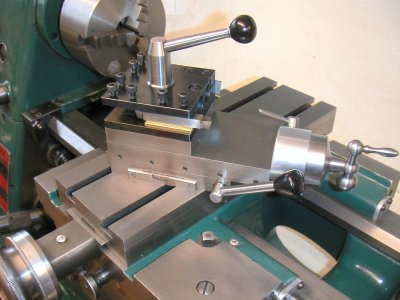
The cross slide was modified by adding tee slots for greater versatility and to mount my lever locking topslide in place of the original topslide. The advantage of this is that it can be moved and locked anywhere at any angle on the cross slide,(Photo 5). The cross slide feedscrew was worn in the middle part. It is a two start thread of 0.200” lead or 5 TPI twice. I set this up in the lathe, which now had no feed screw. I fixed a stop at the end of the cross slide and manually pushed the slide up to the stop on re-cutting the feedscrew and manually withdrew it to return the cutting tool to make another cut.
With the lathe set at 5 TPI, I found that I could make one cut with the screwcutting dial at number one then a second cut at number three. This is when the screw cutting dial has rotated 180 degrees from number one. The purpose of this was to make the second cut along the other screw thread on a two start thread. Using the topslide set parallel to the lathe axis to advance and retract the cut. I cut off just enough so that the worn part was the same as the rest of the screw. Albeit with a thinner thread part and a wider groove between the screw flanks. The reasonably worn nut was cut up to make it adjustable.
I was most pleased with the result; it is about 2 to 3 thou backlash over the entire travel of the cross slide. The end result of my butchery to the lathe bed was that when I was making the vertical column for the Stepperhead lathe I was able to turn a 450mm long, 75mm dia Mild steel bar for the full length to within about 0.0005” and nobody was more pleased and relieved than me.
The standard splash guard on a Chipmaster is a deep affair reaching down nearly to the floor. Where a suds pump is normally located but was missing in my case. This was not a problem for me, as brush application suffices. If you dropped a tool or part, it became a real pain to retrieve it from deep down among the swarf. At the point where the lathe bed sits on its substantial base support is a gap about 5mm wide. I cut a sheet of 6mm plywood to fit the space between the bed and the splash guard with about 15mm angle aluminium fitted to the splash guard to support the other side using self tapping screws. The edge of the plywood was tapered to fit into the gap and rest on the angle support, (Photo 5). The result works very well as anything dropped down can be reached and swarf is easily accessed for cleaning.
I cleaned up the existing three jaw chuck and reground the jaws using a Dremmel. Along time ago I cut a ring of steel into three equal parallel ended segments. These can be positioned between the chamfered faces of the jaws, tightening the jaws with these in place pushes the jaws in a similar manner to the normal operating mode and allows clear access for grinding the jaw contact faces (Photo 14). Ebay supplied a four jaw chuck and a Jacobs Rubber flex chuck but I had to make the chuck holder to fit the lathe.
I have since made a new Lever Locking Topslide, (Photo 8). This features an oval gib of my own design. It enables the whole upper slide to be solidly locked to its base unit for the full slide length.
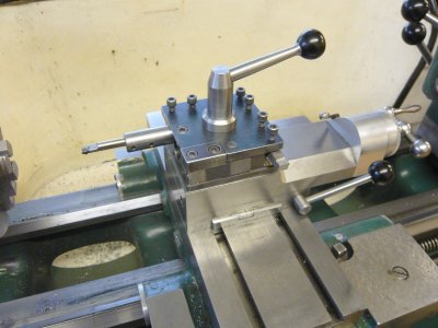
A locking lever is positioned just below the feed dial to do this, (Photo 10). It has a screwcutting withdrawal lever for external/internal screwcutting, the intermediate spindle runs on ball bearings and the long feedscrew nut is machined, not moulded from acetal, and this can be adjusted for backlash on the feedscrew.
It has a choice of toolholders, the triangular one for tipped inserts can be inverted and then mounted on the far side of the item being turned like a rear parting tool, (Photo 11). This is very useful if there is a lot of metal to be removed on a long part, it avoids nearly all the swarf being thrown forwards and seems to assist in getting a good surface finish.
Being able to place the topslide on the far side of the piece being turned is also very useful for screwcutting up to a shoulder or a blind bore. The topslide is set at an angle to suit the thread, say 60 degrees to the lathe centreline. Then the cutting tool is positioned just slightly away from the shoulder with the saddle up against a bed stop. To cut a righthand thread the lathe is run in reverse and when the leadscrew is engaged the cutting tool will move away from the chuck to cut the screwthread. This enables the cut to be applied while the lathe is rotating to form a thread depth undercut and avoids scary moments trying to disengage the leadscrew before the tool hits a shoulder as in the normal method.
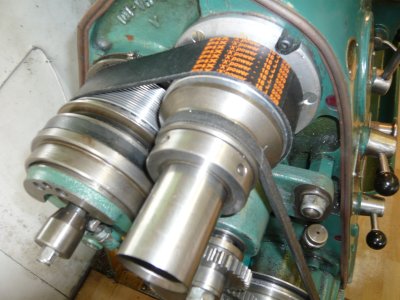
One main feature of a Chipmaster is the toothed belt drive to the mandrel. As good as it is, it still makes a whine due, I guess, to air being forced out of the tooth recesses during rotation. I worked out that I could just about fit a polyvee belt in place instead. Two aluminium sleeves grooved for a wide polyvee belt are pressed onto the existing toothed pulleys. I was going to Loctite them on but it was not necessary. I was lucky my calculations were good, as the belt tension is just right, lucky because there is no space for a jockey pulley anyway, (Photo 6). This new polyvee drive is great; the lathe is like a new machine, so much quieter than before. To be fair, polyvee belts did not exist in 1956 so the toothed belt was the latest technology then (Photo 7).
To finally finish it off I made a set of bed wipers for the saddle. The holes were already drilled and tapped but the original ones were not fitted, I suppose this had to be specified when it was first ordered.
Another nice feature of a Chipmaster is the power feed disengagement up to a bed stop, very useful for boring etc. All in all, it is a great machine, probably a bit under powered, should have got a 2 hp motor instead of 1.5 hp but it is not a problem for most of the things I do and back gear can always be engaged for large diameters etc.
Over time I have added many attachments, a topslide milling/drilling spindle., (Photo 15). A large brass disc scale from an old rusty meat scale has 200 and 180 holes around the periphery. This can be mounted on the outside end of the spindle for indexing, (Photo 16) I have also made a rotary table that can be mounted on the cross slide in the vertical or horizontal. A Harrison vertical slide has also been adapted to fit the cross slide.
It is 60 years old now and is still going strong; it still runs as smoothly as the ones I used at college as an apprentice. It has weathered time very well; I only wish I could say the same thing about its owner!
Photo 1 All cleaned up