Metal Straightedge

Metal
Status
Not open for further replies.

Brian26

Active Member
Premium Member
Advice and comments. please. I just watched a video of an Australian guy making a wooden saw guide to keep his cuts straight. That's quite common on YouTube. What caught my "metalworking" eye was that he used as a reference, a straightedge he obviously acquired somewhere (but doesn't refer to in his video, and no comments at all about it either). Certainly it must have been hollow, and looked to be perhaps 1" x 3" tubing - might be aluminum. At least 6 feet long. So, the question is - if someone needed a decent straightedge made from metal, what's the best way to get there? For the record, many years ago, I bought a 9 foot long cold rolled piece of steel, 2" x 3/8" and had it ground to make it as straight as reasonably possible - for a local sharpening establishment anyhow. The trouble with that is that when I lay it out to use it and secure both ends, I can easily move the middle about 1/32" each way - so it is not as accurate as I want.

For the record, I am not looking to get anywhere close to perfection with this. But +/- 1/32" over 9 feet is not acceptable either. Has anyone made or bought anything close to a decent long straightedge? I have a couple of decent straightedges from Lee Valley, but they top out at 36". Something I might use on an 8-foot sheet of plywood?
 

Brian26

Active Member
Premium Member
I had a track saw until someone stole the saw last March. Oddly enough - left the track!? Good idea though - I will look into that. Might see what aluminum tubing is available.
 

Susquatch

Ultra Member
Administrator
Moderator
Premium Member
My first thought was a track for a track saw. But I think you will find that even a top notch track will bend a 32nd over 9 feet. My brother has a Festool Guide that bent if you pushed on it.

Everything moves with force, it's not if, it's only how much. At 9ft, the leverage is very high.

Frankly, I wouldn't worry so much about it, just cut with it in a way that doesn't apply much bending force to the guide.

Also, I find that 8ft 6" is enough guide for plywood.

My own guide is a 2part Lee Valley Veritas. At first I couldnt see how it could stay straight for 8ft. But it's never let me down.
 

Brian26

Active Member
Premium Member
Good ideas. I actually do use a lateral support for my 9' straightedge whenever I am trying to be super accurate. Keeps the lateral force of, for example a router, from shoving it sideways. But it is an added step, so I am wondering if I am missing some obvious way of making things stronger, lighter and more accurate.
 

Janger

(John)
Administrator
Vendor
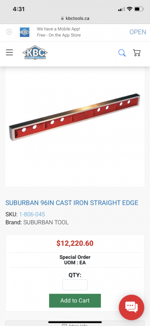
Industrial straight edge. It’s a good idea but…there is a wee problem.
 

Attachments

  • IMG_4212.png
    IMG_4212.png
    504.5 KB · Views: 14

Janger

(John)
Administrator
Vendor
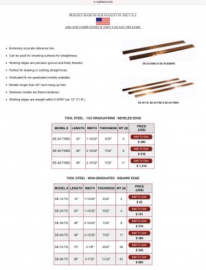
McMaster has a 96” aluminum version for $196usd. Still expensive. I think susquatch suggestion of Lee valley is a good one.

A piece 6” x 1/4” or 3/8” thick by 96” aluminum bar stock would be pretty straight and not flex that much. And still be fairly light to handle. Depends on what tolerance you really want.
 

Dabbler

ersatz engineer
If you need support strength in the order of 50 pounds, and accuracies in the +/- .003 range, then try this: Get a stick of 20' of 1"X3" 1/8 wall or 1/16 wall tubing. Depending on your supplier, perhaps 90$. Cut your 9' piece. Then cut a 7' piece, leaving you with a piece about 4'. Stack them like a symmetric pyramid. If you need more accuracy, drill and tap holes about ever 4 or 5" and use countersunk Allen screws and nuts behind to mount a 9' piece of 1" X 1/2" (or 3/4) cold rolled steel. Calibrate it to be within .001 over the segments and length. (check it in segments on your mill with a test or plunger indicator) This should cost you way less than 200$

Welding note: use very short stitches, around 1/2" long every 6 or 8" to minimize distortion, TIG welding is best.
 
Are you looking for a great straight edge consider machinist wire......


Ideally highly tensioned between two points will will provide a great straight edge to measure from.

Alternatively, caulk line is to a great alternative.
 

Brian26

Active Member
Premium Member
If you need support strength in the order of 50 pounds, and accuracies in the +/- .003 range, then try this: Get a stick of 20' of 1"X3" 1/8 wall or 1/16 wall tubing. Depending on your supplier, perhaps 90$. Cut your 9' piece. Then cut a 7' piece, leaving you with a piece about 4'. Stack them like a symmetric pyramid. If you need more accuracy, drill and tap holes about ever 4 or 5" and use countersunk Allen screws and nuts behind to mount a 9' piece of 1" X 1/2" (or 3/4) cold rolled steel. Calibrate it to be within .001 over the segments and length. (check it in segments on your mill with a test or plunger indicator) This should cost you way less than 200$

Welding note: use very short stitches, around 1/2" long every 6 or 8" to minimize distortion, TIG welding is best.
So - weld the three different lengths together? Steel or aluminum? Would you use shims at all in calibrating the device if I were to add the 1x1/2" cold-rolled piece on the long side? As to adjusting it to a final degree of straightness - I wonder if the idea below might be a good one?
 

Brian26

Active Member
Premium Member
Are you looking for a great straight edge consider machinist wire......


Ideally highly tensioned between two points will will provide a great straight edge to measure from.

Alternatively, caulk line is to a great alternative.
I have learned a new term today - so, a good day! I will look up machinist wire. I presume it is wire with a diameter held to a precise dimension? I like your idea - especially when considering it could be used to calibrate the device described by Dabbler in his reply.
Lots of great ideas. Thanks everyone. I like the idea of a steel straightedge, but not at the price in US$ as mentioned. Probably worth that price to some who make a living using such accuracy, but for myself? Not something I could justify.
 

Dabbler

ersatz engineer
Would you use shims at all in calibrating the device
No need that is what the countersink bolts are for. They hold the cold rolled away from the tubing which is tapped to the screw thread. the nuts go on the backside of the cold rolled. the countersunk bolt screws the cold rolled in/out, and the locking nut freezes everything in place.This calibrating is usually done on a mill, with a half thou indicator. if you 1/4-28 bolts, you can easily hold the cold rolled to .001 tolerance and this structure won't bend under use.
 

Janger

(John)
Administrator
Vendor
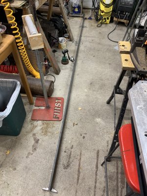
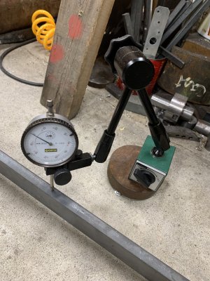
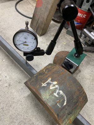
I did a test out of interest. I found a 10’ 2”x1/2” bar stock. Supported it between two drops. Then I put my test indicator on it in the middle and pressed on it with my fingers. It moved 0.05”. With a 3kg weight it moves 0.020”. 1/32” is 0.031” for comparison.

Everything is rubber even a really awkward straight edge. If this bar was something that could be heat treated how flexible would it be after? @Dabbler have you got an equation and some constants for different materials to see the math?
 

Attachments

  • IMG_4214.jpeg
    IMG_4214.jpeg
    707.7 KB · Views: 8
  • IMG_4215.jpeg
    IMG_4215.jpeg
    525.1 KB · Views: 9
  • IMG_4216.jpeg
    IMG_4216.jpeg
    557.8 KB · Views: 8

whydontu

I Tried, It Broke
Premium Member

Dabbler

ersatz engineer
So - weld the three different lengths together? Steel or aluminum?
yes so you end up with a 9" deep sandwich. I'd use 1 X 3 X 3/16 tube. Or whatever you can get. 2 X 4 X 1/8 might be easier, and about the same price - 120 bucks. (and a 12" deep sandwich).

If this bar was something that could be heat treated how flexible would it be after? @Dabbler have you got an equation and some constants for different materials to see the math?
Harder materials are stiffer, but they still bend. It is related to the tensile strength and depth of web. So a high tensile thin rod is just about a stiff as a low tensile one. But a high tensile bar that is 6" thick in the direction of force is a *lot* stiffer than a low tensile one.

Your best stiffness comes from cross section - it is geometric, but tensile strength is a linear modifier.

[just up] Engineers power tools is a great resource. You don't have to look up a bunch of formulas if you use it.
 
Last edited:

Dabbler

ersatz engineer
In the early 2000s they discovered that Osmium, a fairly soft material compared to diamond, has a higher bulk modulus. Bulk modulus is easier to measure that the related modulus of elasticity , which is the property that, combined with tensile strength give the greatest stiffness in structures.

Practically speaking the stiffest structures which we are referring to here, are a combination of tensile strength and EDIT > high resistance to compression.

So the most "likely candidate" is graphene bonded with plastic resins, but it will be many years to become a usable material. Closest to being able to be produced commercially is barium titanate. The most practical available one? Likely Titanium at high cost. For the win "Cost vs stiffness"? White iron. I was previously aware of the Osmium and graphene discoveries. For me barium titanate is brand new.
 
Last edited by a moderator:

Mcgyver

Ultra Member
Industrial straight edge. It’s a good idea but…there is a wee problem.

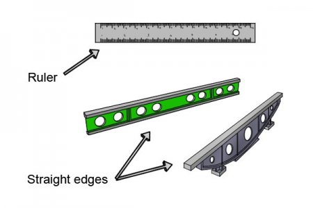
The nomenclature gets a bit muddled in that the references flats a scraper uses, e.g. a camel back, are also commonly called straight edges. I think that is a crappy handle....."reference flat" would be more descriptive and appropriate imo. Nevertheless if you search for straight edge you'll see a lot of what are what I call reference flats... which are likely going to be more expensive and perhaps not what you are after. I've got reference flats (camel backs) up to 60" (I can barely lift it) and a 72" Starrett straight edge (still waiting for its first application) I picked up somewhere along the way but for wood working I'd reach for a track saw track thinking it would be good enough.


1698058879242.jpeg
(image from here https://www.wonkeedonkeetools.co.uk...s-an-engineer-s-straight-edge#google_vignette )
 

Brian26

Active Member
Premium Member
No need that is what the countersink bolts are for. They hold the cold rolled away from the tubing which is tapped to the screw thread. the nuts go on the backside of the cold rolled. the countersunk bolt screws the cold rolled in/out, and the locking nut freezes everything in place.This calibrating is usually done on a mill, with a half thou indicator. if you 1/4-28 bolts, you can easily hold the cold rolled to .001 tolerance and this structure won't bend under use.
OK - I can now see how this works. Thank you very much for the idea. Although - a nearly 10" wide solution was not quite what I was looking for, mainly because it would be difficult to use close to the edge of a piece of plywood.
 
Status
Not open for further replies.
Top