Rpm Sensor (missing)

MecGen

Member
Hello people.

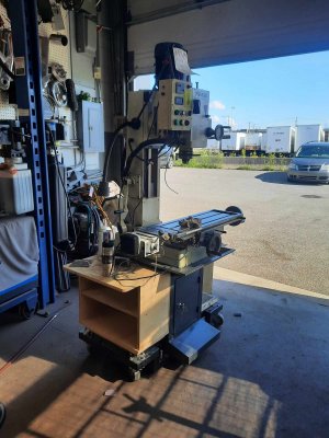
I just purchased my first mill, PM-45M. It's going to take some work to put it in shape. This mill will have a complete service this winter but I thought I would look for some parts right away.
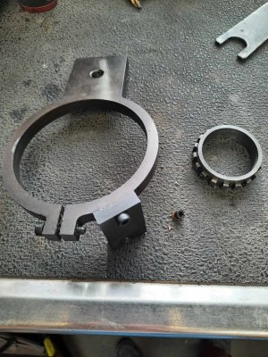
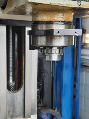
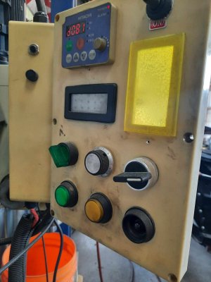
The machine has a VFS and a RPM display, but the RPM sensor is gone - suspected crash. I have found a ton of "kits" that work with a magnet (have one on my lathe) but this differs as it uses a steel reluctor (teeth) and the sensor is very small. There is no magnet in the reluctor, and it looks to have been a very small sensor as the sensor holder has a 8x1.0mm threaded hole, that had a reducer or a bushing to hold the sensor. 12 volt.
Does anyone know of a part number, or even the proper terminology for the sensor - Hall effect, pnp, npn, etc... ? I found a ton of larger sensors that seem like they can work but they are too large, 3/8 thread, and I am sure they are not ment for small reluctant teeth - leading edge is too close to the trailing edge. I looked at the PM site and they make no mention of a sensor, and I am sure this is an add on.
Any help will be appreciated, Cheers

I did not take a pic in the right angle to see how the sensor is mounted, sorry.
 

Attachments

  • received_153315157825451.jpeg
    received_153315157825451.jpeg
    392.7 KB · Views: 13
  • received_267478616228469.jpeg
    received_267478616228469.jpeg
    145.9 KB · Views: 13
  • received_3156190884687437.jpeg
    received_3156190884687437.jpeg
    137.8 KB · Views: 14

Susquatch

Ultra Member
Administrator
Moderator
Premium Member
On first blush, it looks like a proximity sensor. The kind used on the flywheel of your car engine.

You can prolly make it work, but why not make it yours? Start fresh with a new design of your own that you are familiar with.

For the time being, you can make a chart with speed, gear, and frequency on it.
 

Larry_C9

Super User
Premium Member
The Craftex CX601 mill has a pretty small sensor at the top of the spindle. It runs on 5Vdc according to the wiring diagram. It has 3 wires going to it from one of the circuit boards. I could take the cover off and get a picture if that would help. I believe I also have the Craftex part number for it.
 

MecGen

Member
On first blush, it looks like a proximity sensor. The kind used on the flywheel of your car engine.

You can prolly make it work, but why not make it yours? Start fresh with a new design of your own that you are familiar with.
Thought of that, but this RPM sensor is wired through the VSF so I don't know if it is specific to the number of teeth on the reluctor.
 
Last edited:

MecGen

Member
You have already tried contacting PM by phone or email?
Yes, but in all honesty I hate asking a supplier something like that ... because most likely I will find it elsewhere les expensive. I don't want to fish for info (unless I am stuck) just to buy it somewhere else. I am also not for sure if this rpm was an add on or bought from PM.
 
Last edited:

MecGen

Member
The Craftex CX601 mill has a pretty small sensor at the top of the spindle. It runs on 5Vdc according to the wiring diagram. It has 3 wires going to it from one of the circuit boards. I could take the cover off and get a picture if that would help. I believe I also have the Craftex part number for it.
That's very nice of you but I am looking for a 12 volt sensor as it is wired through my VFS.
 

Susquatch

Ultra Member
Administrator
Moderator
Premium Member
Thought of that, but this RPM sensor is wired through the VSF so I don't know if it is specific to the number of teeth on the reluctor.

Acronyms drive me crazy sometimes when they are not obvious. What do you mean when you say VSF? Best I can do is Variable Speed F???

Put an Oscilloscope on the sensor and turn the spindle. You should know rather instantly. But I am almost certain that's what it is.

If so, then yes. It will be exactly specific to the number of teeth. To be honest, that thing you call a reluctor is what I would call a speed gear, and that is why I think it is a proximity sensor. A reluctor requires a magnet on one side and a hall effect on the other. The teeth then act like a shutter for the magnetic field. A hall effect can also be used with rotating magnet(s). A proximity sensor detects the passing gear tooth.
 

MecGen

Member
Acronyms drive me crazy sometimes when they are not obvious. What do you mean when you say VSF? Best I can do is Variable Speed F???

Put an Oscilloscope on the sensor and turn the spindle. You should know rather instantly. But I am almost certain that's what it is.

If so, then yes. It will be exactly specific to the number of teeth. To be honest, that thing you call a reluctor is what I would call a speed gear, and that is why I think it is a proximity sensor. A reluctor requires a magnet on one side and a hall effect on the other. The teeth then act like a shutter for the magnetic field. A hall effect can also be used with rotating magnet(s). A proximity sensor detects the passing gear tooth.
I get what you are saying. I guess the acronym I are looking for is VFD. When I purchased this mill there was no sensor just a harness that appeared to be torn - hence why I think there was a collision.
I have searched "hall effect sensor" and found only the type where you install a magnet and it counts as 1 revolution when the magnet passes, not 12 shutters. It is possible that the VFD can be programmed to accept the popular sensor, and the bonus would be I could mount the sensor on the top rather then the bottom near the work.
I got a feeling I am going to have to rework the electronics.
I am a retired auto tech so these types of electronics are not hard for me to figure out, it's just getting to know the terminology and understand some of the basic components. I have even thought about using an ABS sensor.

Thanks for taking the time to help. Cheers
 

Susquatch

Ultra Member
Administrator
Moderator
Premium Member
I get what you are saying. I guess the acronym I are looking for is VFD.

OK, this makes total sense now. Assuming that is right, I believe your vfd is using a sensor to read speed and uses that feedback to refine the output speed of the motor under load.

But you will be pleased to know that modern VFD's can read excellent speed using the back emf from the motor. It's called sensorless vector mode. Google "VFD sensorless vector".

So if you want, you can dump the whole speed input.

When I purchased this mill there was no sensor just a harness that appeared to be torn - hence why I think there was a collision.
I have searched "hall effect sensor" and found only the type where you install a magnet and it counts as 1 revolution when the magnet passes, not 12 shutters.

All Hall effects use a magnet. But they can be setup to use as many magnets as the software can handle.

When I get to it, my lathe will have at least 4 mounted in an ABS Collar. They will be used for an rpm display only. The VFD will run in sensorless vector mode.

Your 12 teeth have no magnet so that's why I think its a proximity sensor.

It's good that you are an auto tech. That knowledge will serve you well machining.

Basically, your sensor works just like a crankshaft position sensor in an engine. The position is used by the VFD to maintain the mills motor speed under load.

It is possible that the VFD can be programmed to accept the popular sensor, and the bonus would be I could mount the sensor on the top rather then the bottom near the work.

Yes, it's possible, but not as good. The common top sensor systems only have one pulse per revolution. The VFD is happier with lots more. But no worries, you can skip the whole enchilada now and go sensorless vector.

I got a feeling I am going to have to rework the electronics.
I am a retired auto tech so these types of electronics are not hard for me to figure out, it's just getting to know the terminology and understand some of the basic components. I have even thought about using an ABS sensor.

You will be just fine! Lots of guys on here who are wizards and like to help.

Thanks for taking the time to help. Cheers

Our pleasure!

Tell us more about your motor?
 

jcdammeyer

John
Premium Member
Here's a bit of a write-up on hall sensors. You can get them so they sense vanes on a disk. I had one like that from Honeywell but it had a collision with the disk and I never did replace it.
Edit: Forgot link.
 
Last edited:

MecGen

Member
It's called sensorless vector mode. Google "VFD sensorless vector".


Your 12 teeth have no magnet so that's why I think its a proximity sensor.

It's good that you are an auto tech. That knowledge will serve you well machining.

Basically, your sensor works just like a crankshaft position sensor in an engine. The position is used by the VFD to maintain the mills motor speed under load.

Tell us more about your motor?

I just checked my Hitachi SJ-200 manual, and it does have the sensorless vector mode, so that is a great option. I thought the RPM sensor was just for the display but yes it makes perfect sense the VFD can adjust for load. My control panel does have a separate potentiometer that does control speed, the small dial on the Hitachi display does nothing, but it shows an error (not surprised).

I found this mill in a woodshop. The employee said it leaked a bunch of oil on a expensive piece of wood so it was replaced with a bigger, new machine. It came with an X and Z axis motors (z has stripped gears but functions), VFD, oil pump/reservoir, but no tooling. This winter, things will come apart, seals replaced, and get all the bugs ironed out.

My goal is to get this running with min trouble to see if I still have the "learning ability" to make this a worthwhile addition... I am absolutely floored with the cost of tooling, auto mechanics is bad enough but to start at zero with a mill ... I don't know, time will tell. Thankfully I got the mill at a great deal, $500+$150 parking ticket+day/gas/transport so I can't really go wrong. Being an older mechanic, back in the good ole days, I worked hand and hand with my machine shops, but never IN a machine shop so lots of things to learn.

Cheers
 

Attachments

  • received_1010479250674146.jpeg
    received_1010479250674146.jpeg
    166.9 KB · Views: 12
  • received_275694475413357.jpeg
    received_275694475413357.jpeg
    137.9 KB · Views: 12
  • received_1004052937409729.jpeg
    received_1004052937409729.jpeg
    224.8 KB · Views: 12

Susquatch

Ultra Member
Administrator
Moderator
Premium Member
Beautiful! Thanks for the motor info. After looking at that, I think that the motor and speed control are the least of your worries. The motor is 2HP 3phase VFD Rated for 3 to 60Hz configurable to 220V. NICE!

You don't even need that sensor system so cross that one off your must-do list. You can always fix it or redesign it if you want the rpm readout. It's good that you don't HAVE TO though.

Right now, my own mill has no RPM Readout. It's on my to do list but it's a want not a need. For now, I have a chart taped to the head of my mill that converts gear to RPM for when I need it. The change in RPM due to Frequency is just a linear interpolation I can do in my head.

I have my VFD set to a minimum Frequency of 6 Hz. Yours can do 3 Hz. I'd set that to 6 anyway. Your motor is listed at a max of 60, but I'd push that to 75 if it were mine.

No fair including parking tickets in the cost of the mill. Your bride wouldn't include that if she was buying a new microwave.......

Not sure how old you are. I'm 77. Sitting on my butt was not an option when I retired. I'd be dead by now if I did. Machining is a great hobby for old guys. So is fixing old machines. Take your time and enjoy yourself. There are lots of folks on here who will help you. As a mechanic, you already have the problem solving mechanical talents you need. The biggest problem we all have is the money to buy what we want need.

In the meantime, you can stop worrying about your sensor system. That's an optional fix.

Lots of ways to do an rpm display if you feel you really need it (IMHO you don't.)

What else is wrong with that machine?
 

MecGen

Member
What else is wrong with that machine?

Nothing really, the big heavy z axis motor Al-510 has a stripped plastic gear, and probably needs an overhaul - it was removed and tossed in a box. The x axis motor is poorly mounted. I have a feeling these were removed to try to fit them to the new mill ... I found an adjustment nut inside the was backed way off - excessive backlash on the quill.

I was chasing the owner through FB for a couple weeks, he was on vacation, I managed to find an employee and made the deal in 2 minutes.

In full disclosure, I am semi retired, I work when I feel like it, as tech support for an oil company. 57 this year.

Thanks for everything.
 

Susquatch

Ultra Member
Administrator
Moderator
Premium Member
Nothing really, the big heavy z axis motor Al-510 has a stripped plastic gear, and probably needs an overhaul - it was removed and tossed in a box. The x axis motor is poorly mounted. I have a feeling these were removed to try to fit them to the new mill ... I found an adjustment nut inside the was backed way off - excessive backlash on the quill.

I was chasing the owner through FB for a couple weeks, he was on vacation, I managed to find an employee and made the deal in 2 minutes.

In full disclosure, I am semi retired, I work when I feel like it, as tech support for an oil company. 57 this year.

Thanks for everything.

Great story. Sounds like you are off to the races!

You will enjoy membership here. Just scream HELP when you need it, ask a question of any kind, or Hi-Jack a thread when it prompts a thought.
 
Top