• Scam Alert. Members are reminded to NOT send money to buy anything. Don't buy things remote and have it shipped - go get it yourself, pay in person, and take your equipment with you. Scammers have burned people on this forum. Urgency, secrecy, excuses, selling for friend, newish members, FUD, are RED FLAGS. A video conference call is not adequate assurance. Face to face interactions are required. Please report suspicions to the forum admins. Stay Safe - anyone can get scammed.

Rotary Table question

Tomc938

Ultra Member
Premium Member
So I have my first project using my rotary table and I have a set-up question:

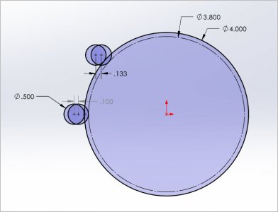
I will be turning the outer hub of a brake disk to be used as a mounting pillar for a telescope. (Surface "A" in the picture)

I am thinking it doesn't matter if the table is centered, as I will move the piece into the tool, and then simply rotate the table. The table won't move in relation to the tool, except around it's centre axis, so it will take the same amount of material off all the way around the part.

What I will need to do (carefully) is centre the part on the table so I don't end up with some sort of eclipse.

Am I right, or am I missing something?

Thanks in advance!

Tom

PS: Unfortunately, It's too big to fit on my lathe without a lot of fixturing.

Disk.jpeg
 

YYCHM

(Craig)
Premium Member
I assume you are planning to mount the RT horizontally on the mill table? The RT will have to be centered under the spindle and the part centered on the RT (i.e. the spindle).

Sure looks like a job for the face plate on your lathe to me. Setup time on the RT or face plate will probably be about the same with the lathe producing better results.

Are you sure you can't grab it from behind with the outside jaws of your 3J lathe chuck?
 

jcdammeyer

John
Premium Member
This is what I do. In the photo you see resting on the chuck is an alignment tool. It's tapered to fit into the rotary table and just long enough so the chuck jaws can grab it. So tapped into the MT-2 rotary table without the chuck mounted I can either grab the end in a collet or with the drill chuck depending on how precise I want to be. That lines up the center of the rotary able with the spindle. Bolt it down onto the table. Set DRO x,y to 0,0.

Next I lower the 3 jaw over the tool and lightly tighten the jaws. Now the chuck is centered on the rotary table. Bolt it down. Loosen 3-jaw and remove alignment tool.

Clamp whatever you want into the jaws and machine however you want.
RotaryTableAlignment.jpg

Here's an example of how I used it. With the center of the rotary table set to 0,0 and LinuxCNC set to 0,0 and the AlibreCAD and AlibreCAM set to 0,0 the generated G-Code profiled this hub along with the protrusions for set screws.

Yes it could be done manually by setting the entry point with the rotary table, in with the X axis to depth of cut and then rotate the table until the next exit point. Repeat at each depth.

SpringCollar-Machining-2.jpg
 

jcdammeyer

John
Premium Member
Oh and the reason I made this out of metal is because the plastic just wasn't strong enough.
SpringCollar-Done.jpg

And since I really don't like it when people show a part being made but not where it goes the photo below shows what it's for. It sets the return spring tension for the power draw bar. I didn't have metric set screws so I used two different length screws so the heads wouldn't interfere with each other. Top half internal diameter is for the 1/2" copper pipe and the bottom half is for the guide rod.

TrialFitOnSpindleCover-1.jpg
 

garageguy

Super User
Premium Member
Good replies previously. This would be a good job for a lathe but if that's not an option a milling machine will do. One thing to keep in mind is that the cutter will impart rotational torque on the RT so make sure your setup is really solid and that your RT can handle the torque.
 

Susquatch

Ultra Member
Administrator
Moderator
Premium Member
Am I right, or am I missing something?

You sure you don't know somebody with a big enough lathe for that job........

If you are hell bent to use your mill, I don't think you need the table precisely located. You just need the disc precisely centered on the table.

Maybe you already told us, but where are you located?

Telescope? Did somebody say telescope? I love astronomy too! Please tell us more about what you are doing!
 

phaxtris

(Ryan)
Premium Member
Premium Member
I think you definitely must have the brake rotor centered on the rotary table, or you are going to end up making that center hub into an eccentric relative to the other round parts
 

mickeyf

Well-Known Member
"It's too big to fit on my lathe without a lot of fixturing"

I would jump through whatever hoops I needed to to be able to do this on my lathe. A lathe is designed for things like this. A rotary table to my thinking is for portions of a circle, like slots or holes that most be x degrees long or apart from each other, or a "broken" circle such as jcdammeyer shows. If the overall diameter is not more than your lathe can swing there are likely several ways to approach it. Bolting to a face place using the existing holes is probably the most obvious.
 

VicHobbyGuy

Ultra Member
I am thinking it doesn't matter if the table is centered, as I will move the piece into the tool, and then simply rotate the table. The table won't move in relation to the tool, except around it's centre axis, so it will take the same amount of material off all the way around the part.

What I will need to do (carefully) is centre the part on the table so I don't end up with some sort of eclipse.

Am I right, or am I missing something?
Unlike the other more experienced responders, I think you are correct. The distance between the center of the table/center of the workpiece and the mill spindle/cutting tool won't change if the workpiece is centered on the rotary table.
 

Susquatch

Ultra Member
Administrator
Moderator
Premium Member
Unlike the other more experienced responders, I think you are correct. The distance between the center of the table/center of the workpiece and the mill spindle/cutting tool won't change if the workpiece is centered on the rotary table.

I think you are misreading the "more experienced users". By my read, they all agree with you. I certainly do. My own only caveat is that the work must be centered on the axis of the ROTARY table. I don't really care where the rotary table is located on the table.

I think all the confusion is about which table folks are referring to. The experienced folks on here prolly all ASSUME when people say table, they mean ROTARY Table.
 

VicHobbyGuy

Ultra Member
I think you are misreading the "more experienced users". By my read, they all agree with you. I certainly do.
Perhaps I misread some of the posts (??), but.....
I was referring to:
I assume you are planning to mount the RT horizontally on the mill table? The RT will have to be centered under the spindle and the part centered on the RT (i.e. the spindle).

This is what I do. In the photo you see resting on the chuck is an alignment tool. It's tapered to fit into the rotary table and just long enough so the chuck jaws can grab it. So tapped into the MT-2 rotary table without the chuck mounted I can either grab the end in a collet or with the drill chuck depending on how precise I want to be. That lines up the center of the rotary able with the spindle. Bolt it down onto the table.
 

jcdammeyer

John
Premium Member
When I wrote my description of setting up my rotary table I made an assumption that may not be valid.
That Tomc938 has a 3 jaw chuck mounted on the rotary table. If there is no chuck then the brake disk will be bolted directly to the table.

So then it just become an exercise on aligning the disk onto the table. Doesn't matter where the rotary table sits. Just spin it around with a dial on it until the deflection is within whatever tolerance is desired.

Now if there are a number of holes that need to be drilled relative to the center of the disk, for mounting the telescope for example, then you still need to figure out where to put them. It's easiest to already have the rotary table aligned with the spindle at 0,0. Then if you want 4 holes on a 3" radius just move over 3" and drill the first. Rotate table 90 degrees and drill the next. Rinse and repeat.

It really all depends on the precision required. My tapered tool for my rotary table just makes a lot of those things really easy.
 

PeterT

Ultra Member
Premium Member
There is a somewhat practical reason for pre-centering the RT to spindle X&Y beforehand even though it may not seem to matter initially. More than likely you will be advancing the cutter in one of the mill table X or Y directions, progressively in-feeding until you achieve a target diameter. If your cutter is off in space, it will require doing some math to compute how much table movement equates to actual diameter as you converge to the target dimension. Hopefully sketch makes sense. Note the 2 different dimensions to achieve the same resultant diameter.

Personally I recommend following the same setup steps every time the RT comes out. It doesn't take long with practice & a good habit to prevent mess-ups. Zero the rotation angle with backlash out & lock table. DTI zero spindle to RT center hole. Mount secondary self-centering holding fixture like 3J chuck to RT platen such that it registers DTI zero on dowel or whatever. Additional gyrations may be required if its holding an irregular part with a center or edge datum vs aforementioned circular parts.
 

Attachments

  • SNAG-2022-08-23 6.53.22 PM.jpg
    SNAG-2022-08-23 6.53.22 PM.jpg
    47.1 KB · Views: 5

Susquatch

Ultra Member
Administrator
Moderator
Premium Member
Perhaps I misread some of the posts (??), but.....
I was referring to:

I'm gunna guess it's all clear to you what they meant now!

FWIW, I feel your pain. The experienced members on here are all REALLY SHARP COOKIES! I never assume they don't know what they are doing. I start out assuming I either didn't understand or I misread what they wrote or I'm gunna learn something new. I'm not shy about learning new things. If I knew everything, I wouldn't need advice from others on here! Sometimes it's better to just start by asking why they recommend whatever they say they recommend doing. I might not agree with it when the dust settles, but I almost always learn something that way!

There really is an amazing bunch of characters on here!

Edit - Oh yes, and lest I get left out, my own comments still stand. I had not gotten to the point where you gotta figure out where the spindle is cuz.... You guessed it! I assume that everyone knows ya gotta do that sooner or later. Some of the advice above is to do it sooner, and mine is to do it later. But ya always gotta do it!
 
Last edited:

Susquatch

Ultra Member
Administrator
Moderator
Premium Member
So @mickeyf , tell us about this telescope of yours and what the brake rotor is all about......

Some kind of new fangled equatorial mount?
 

Tomc938

Ultra Member
Premium Member
On a slightly different note - how do you delete your picture from your profile??

Because I can't show my face on the forum for a while.

In the spirit of Quinn, who always shows her screw ups: While double checking that I couldn't grab inside the hub on the outer drum, (opposite side from "A" side) I discovered that I COULD grab the inner hub with the smallest step on the jaws. Goes to show when you have an idea stuck in your head it might be a good idea to step away and come at it again fresh.

Of course this was after I took my vice off the milling machine table, and lifted the too large rotary table into place. Gotta build a little crane like Mr. Pete.

The mount is for a friends telescope. He found the plans online that call for the modification of a standard size brake disk. It's called a "Pier adaptor."

On the slightly humorous side, he told me the measurement is -0.75/-0.50, which is what someone has on the CAD sheet from Celestron.


Thanks for helping me look at this with fresh eyes. While I have the rotary table mounted, I think I'll give it a whirl with some scrap Al.
 

phaxtris

(Ryan)
Premium Member
Premium Member
On a slightly different note - how do you delete your picture from your profile??

Because I can't show my face on the forum for a while.

In the spirit of Quinn, who always shows her screw ups: While double checking that I couldn't grab inside the hub on the outer drum, (opposite side from "A" side) I discovered that I COULD grab the inner hub with the smallest step on the jaws. Goes to show when you have an idea stuck in your head it might be a good idea to step away and come at it again fresh.

Of course this was after I took my vice off the milling machine table, and lifted the too large rotary table into place. Gotta build a little crane like Mr. Pete.

The mount is for a friends telescope. He found the plans online that call for the modification of a standard size brake disk. It's called a "Pier adaptor."

On the slightly humorous side, he told me the measurement is -0.75/-0.50, which is what someone has on the CAD sheet from Celestron.


Thanks for helping me look at this with fresh eyes. While I have the rotary table mounted, I think I'll give it a whirl with some scrap Al.

I was kinda wondering to myself why you couldn't just chuck it up on the inside of the rotor....but then I thought maybe you just wanted to use your rotary table ? Seemed like good enough reason to me
 
Top