• Scam Alert. Members are reminded to NOT send money to buy anything. Don't buy things remote and have it shipped - go get it yourself, pay in person, and take your equipment with you. Scammers have burned people on this forum. Urgency, secrecy, excuses, selling for friend, newish members, FUD, are RED FLAGS. A video conference call is not adequate assurance. Face to face interactions are required. Please report suspicions to the forum admins. Stay Safe - anyone can get scammed.

RF30 head alignment guide

DavidR8

Scrap maker
Administrator
Moderator
Premium Member
I started building the head alignment guide for my RF mill today.
This is inspired by an excellent idea and execution over on Hobby-Machinist.com

RF-30 Clone Head Alignment Guide
https://r.tapatalk.com/shareLink/to...ent-Guide.84270/&share_type=t&link_source=app

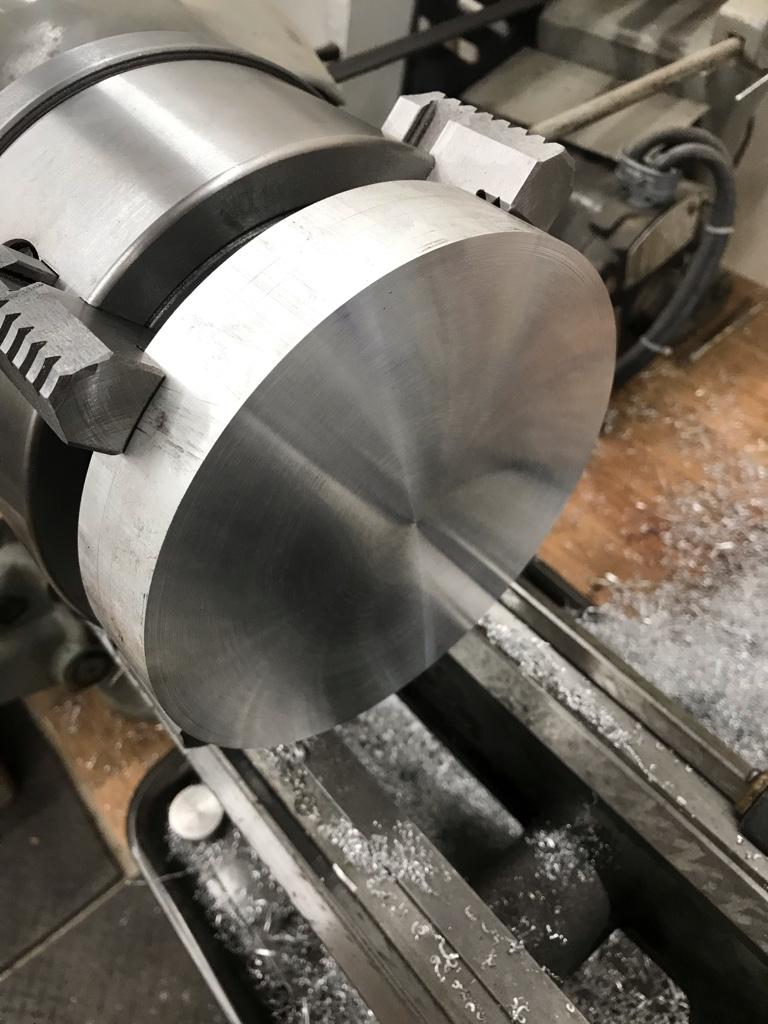
I sourced a piece of 6” diameter 6061 yesterday and today I faced both sides in the 4-jaw.
I hoped to bore it out but got too cold and hungry [emoji39]
63c75e7ed997a2eea2c3659050d34654.jpg


Sent from my iPhone using Tapatalk
 
On the Youtube channel Blondihacks, she was showing the basics of trepanning. Might allow you to save turning a lot of good material into chips?

Craig
 
Major progress today.
Bored it to size.
8ac2e91fa16ea6387e252b405f27396c.jpg


Fitted it up in the mill with a parallel on it face underneath so that the scribed centre line cleared a pair of 1-2-3 blocks on the vise. Using these as references I levelled the ring.
67908b62b09e7e279a3eb866be7ff394.jpg

9f758b26ab30855b896c2f3ce6596c61.jpg

c87cb98892d60ef6b6305f022a54b14d.jpg


I marked the centre of the ring rim and drew a vertical line amd extended it across the top as a reference for the end mill.
5d6ead04e9adb719f52347cdc182105a.jpg


Used a center finder and my DRO to find the centre of the thickness and bored the countersink holes for the 1/2-20 cap screws that will hold the two halves together.
667c02c61a346302005204ca024fb2df.jpg


Sent from my iPhone using Tapatalk
 
What are you using for a boring bar?
I did it in three stages:
1) used a 3" hole saw to remove the majority
2) ground a 3/8"HSS blank so that it had side clearance and put it in my boring bar tool holder. Ran that in straight taking 1/8" DOC at a time. Feed rate was .0027/rev. Slow going but 1/8" better than I could do with the boring bar.
IMG_6733.jpg

IMG_6734.jpg
3) used my SCLCR boring bar to make the finish passes.
 
Took today off to run errands and get in a little shop time.

Finished the collar for the mill.
59635fc04bbeb7d6efde47ea0fb04330.jpg


Made up the four plugs for the stabilizer tubes. All set to be TIG welded on.
33431e8a05514104b292be1e45e3d13b.jpg


Sent from my iPhone using Tapatalk
 
More progress.
TIGed the bungs into the pipes.
11e8b842181ed4f8011703a29a50c5d9.jpg


Cut the brackets and TIGed the pipes onto them.
4b97f233edfa28e6bc0e558d2088dcae.jpg

d257577e139d39f434a8b6da93862857.jpg

44316f6e450a430cc65e13de95a500dc.jpg


Sent from my iPhone using Tapatalk
 
Finished assembling the parts yesterday.
Works very well.
a19ae0d634508c7b26f0c8bc6f3e86a1.jpg

f666d41266f8300b14335dbea9020ffa.jpg

4dc4f74b2ce61f21a43351becbb00100.jpg


Sent from my iPhone using Tapatalk
 
Interesting set up (in a good way).
Are you sure someones race car isn't missing some suspension parts. ;)

Let’s just say that my Formula 3000 bid took a hit :)


Sent from my iPhone using Tapatalk
 
That's great work David. I wanted to do something similar for my drill press, but my machining skills aren't to your level. I guess I kind of cheated when I got my ironworker and started punching everything instead. I hardly ever use the DP now.

Your solution is elegant. I often wonder why there isn't a commercial product that does this, or at least manufacturers who provide a support collar out of the box. From a marketing perspective, it would allow them to boast about less runout.

But after viewing the pics I've developed an unquenchable desire to go watch "Days of Thunder" again. How odd....

Thanks Pete, I appreciate the positive feedback.
I cannot take any credit for the design, it’s a semi-faithful copy of a design I saw on Hobby-Machinists.com.
It is more elegant than any design I’ve seen. And was dead cheap to build.
I had the angle iron and aluminum plate.
$30 for the aluminum round for the column collar.
$25 for the iron pipe
$13 for the heim joints
$10 for the hardware
All in, $80 :)


Sent from my iPhone using Tapatalk
 
Hmmm, for a drill press I’m wondering if it wouldn’t actually be simpler. On a drill press (mine anyway and like the one David used to own) the rack slews with the table so there’d be no need for a collar. Heim linkages from either side of the table to either side of the head should do it. Or am I under-thinking that?
 
Hmmm, for a drill press I’m wondering if it wouldn’t actually be simpler. On a drill press (mine anyway and like the one David used to own) the rack slews with the table so there’d be no need for a collar. Heim linkages from either side of the table to either side of the head should do it. Or am I under-thinking that?

I miss that press [emoji26]
I think that there needs to be means for the arms to adjust to raising and lowering the table.
Because the table doesn’t have near the same mass or forces acting on it I could see a somewhat simpler setup working well.


Sent from my iPhone using Tapatalk
 
Sometimes I read/look at something 50 times and I just don't get it. This is one of those times. I read the link you sent, and I went over your pictures many times -- drawing a blank.

What alignment issue/challenge are you trying to solve and how does this help (how do you use it)?

I have a standup drill press, with a round column, so this should be making sense, but it isn't. Please enlighten me!

https://canadianhobbymetalworkers.com/threads/the-ultimate-round-column-mill-fix.2517/
 
Sometimes I read/look at something 50 times and I just don't get it. This is one of those times. I read the link you sent, and I went over your pictures many times -- drawing a blank.

What alignment issue/challenge are you trying to solve and how does this help (how do you use it)?

I have a standup drill press, with a round column, so this should be making sense, but it isn't. Please enlighten me!

If you have to raise the head on a round column mill it’s impossible to maintain X-Y position because the head is free to rotate around the column just like the table on a drill press when it’s raised or lowered.
This setup prevents the head from rotating as it’s raised or lowered.


Sent from my iPhone using Tapatalk
 
Back
Top