Brent H
Ultra Member
A while back I was asked to make some new gears for a 10” Utilathe. I machined them to standard dimensions but they needed a few more thou off the depth to allow for proper backlash and engagement with the other original gears.
After setting up and taking a skim off the gears I reassembled the head stock. Here is some information if you ever have to do it:

This is the new shaft and reduction gears fitted. There is a new bushing in the left casing and a new roller bearing in the right. This was pressed on. Also on the shaft is the inner race if a needle bearing. This race is used as a smooth wear surface where the shaft seal is fitted. Quite clever. If there is a groove worn you can flip this around to change the running surface.
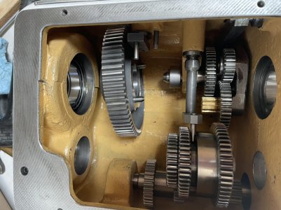
The next part is important. The middle shaft WILL NOT ALLOW THE BULL GEAR TO BE INSTALLED if you fit the middle gearing without placing the bull gear into position like so:

Then you can slide the middle shaft into the headstock and slip on the gears as you go. The middle shaft is keyed - make sure the key is in good order and the gears can easily slide. In the above picture the red circle is a set screw that retains the bearing spacer for the middle shaft. Be sure this is backed out prior to any disassembly or re-assembly or you will cause damage. There was some damage at this location:

You can see that notch - Inused some RTV to seal this as it was leaking oil.

The above is the middle shaft. On my one utilathe the key is retained by screws. This one does not have the screws - very odd but just about ever lathe I see has some differences.
Once the middle shaft is in place there is a bearing spacer

On the left, then the bearing. Be sure to engage the lever (yellow arrow) as you slide the assembly in. On the right is another ball bearing and the set screw located bearing retainer. Once this is together you should move the speed control and make sure all the gears line up and spin properly. In theory it should all be fine. If not, you could machine or add a spacer to locate the gears properly by shifting the shaft left or right.
The main shaft (red arrow) gets slid in through the bull gear and then through the high/low change gear (blue arrow). You need to be sure the splines are lined up as well as the engagement lever. It takes some work to keep the gears all aligned and free - take your time. The main shaft is supported by a conical bearing at the right and a deep groove ball bearing on the left. The main shaft is tapped into place with a dead blow. A nut is threaded on and tightened up. Tighten until you get resistance in spinning the shaft. Back off 1/4 turn, tap the left end of the shaft to set the conical bearing. The shaft should spin freely without any play. Tighten up the locking screw.
Move the headstock through all the gears and make sure everything is free and working.
After setting up and taking a skim off the gears I reassembled the head stock. Here is some information if you ever have to do it:
This is the new shaft and reduction gears fitted. There is a new bushing in the left casing and a new roller bearing in the right. This was pressed on. Also on the shaft is the inner race if a needle bearing. This race is used as a smooth wear surface where the shaft seal is fitted. Quite clever. If there is a groove worn you can flip this around to change the running surface.
The next part is important. The middle shaft WILL NOT ALLOW THE BULL GEAR TO BE INSTALLED if you fit the middle gearing without placing the bull gear into position like so:
Then you can slide the middle shaft into the headstock and slip on the gears as you go. The middle shaft is keyed - make sure the key is in good order and the gears can easily slide. In the above picture the red circle is a set screw that retains the bearing spacer for the middle shaft. Be sure this is backed out prior to any disassembly or re-assembly or you will cause damage. There was some damage at this location:
You can see that notch - Inused some RTV to seal this as it was leaking oil.
The above is the middle shaft. On my one utilathe the key is retained by screws. This one does not have the screws - very odd but just about ever lathe I see has some differences.
Once the middle shaft is in place there is a bearing spacer
On the left, then the bearing. Be sure to engage the lever (yellow arrow) as you slide the assembly in. On the right is another ball bearing and the set screw located bearing retainer. Once this is together you should move the speed control and make sure all the gears line up and spin properly. In theory it should all be fine. If not, you could machine or add a spacer to locate the gears properly by shifting the shaft left or right.
The main shaft (red arrow) gets slid in through the bull gear and then through the high/low change gear (blue arrow). You need to be sure the splines are lined up as well as the engagement lever. It takes some work to keep the gears all aligned and free - take your time. The main shaft is supported by a conical bearing at the right and a deep groove ball bearing on the left. The main shaft is tapped into place with a dead blow. A nut is threaded on and tightened up. Tighten until you get resistance in spinning the shaft. Back off 1/4 turn, tap the left end of the shaft to set the conical bearing. The shaft should spin freely without any play. Tighten up the locking screw.
Move the headstock through all the gears and make sure everything is free and working.