Good video. That spindle nose looks abused, as in beat. If chips caused that I wonder what the guy on the end of the wrench was thinking. Must have taken a lot of force to compress swarf to make those kind of divots in hardened steel.
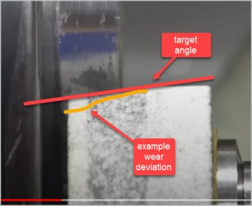
I wonder why he ground the nose angle on the stone & plunged axially? To my thinking, if the dress angle is off a teeny bit, or the stone wears/degrades different based on spindle conditions or grinding dwell time as the job progresses, the stone angle could drift off & therefore spindle angle not be (as) true. ie. why not pre-set the compound using a sine bar or whatever, leave the stone cylindrical & axial & parallel to spindle axis. The corner of the wheel would do the cutting & any wear would not matter as its always traversing in the correct angle.
He made some very good points about how the D-system is supposed to fit to both surfaces simultaneously. And at some point there can be adverse issues as to the camlock fit. I'm not quite sure how one could tune them after the fact. Taking material off them might be doable, but the reverse would not be as straightforward.