• Scam Alert. Members are reminded to NOT send money to buy anything. Don't buy things remote and have it shipped - go get it yourself, pay in person, and take your equipment with you. Scammers have burned people on this forum. Urgency, secrecy, excuses, selling for friend, newish members, FUD, are RED FLAGS. A video conference call is not adequate assurance. Face to face interactions are required. Please report suspicions to the forum admins. Stay Safe - anyone can get scammed.

Pushrod tubes

PeterT

Ultra Member
Premium Member
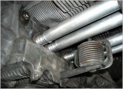
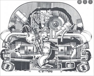
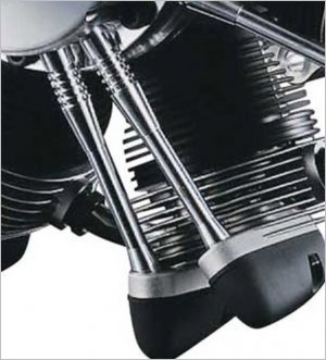
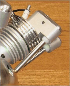
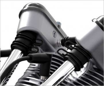
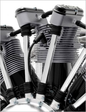
Motor guys: On engines with pushrod tubes like the stainless ones (maybe they are called 'windage' tubes?)
- does the accordion section allow some minor bending or deviation of the tube axis like when the pushrod has to act at a 3D angle from the tappet to the rocker arm?
- or is the accordion more intended like a spring to exerting a bit of axial force to keep the tube in position?
- I assume the accordion has a formed uniform section, as opposed to just grooves cut in? (guessing grooves would fatigue & crack).

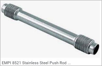
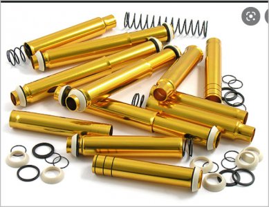
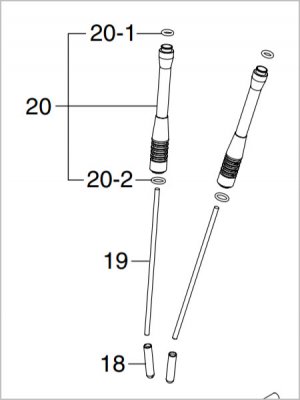
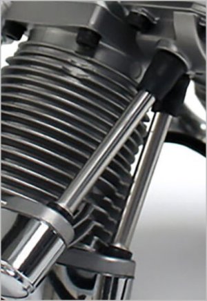
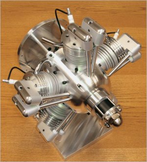
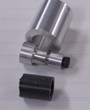
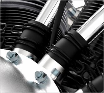
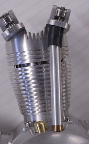
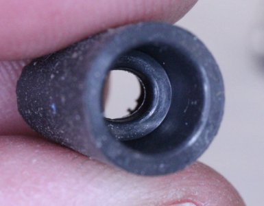
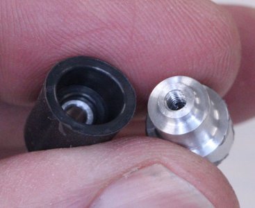
These anodized ones look different. Looks like they have curved rubber seal on both ends & the tube telescopes with a spring to keep them engaged. I can see how this would make installation a bit easier but again mostly I'm wondering if those seals are meant to allow the tube ends to be at a 3D angle to one another?

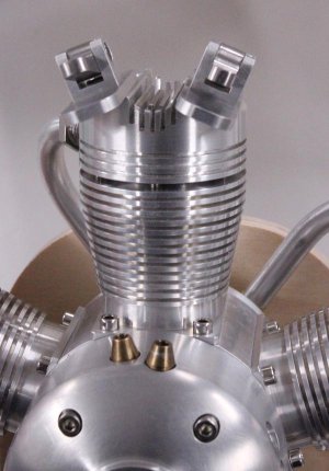
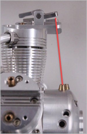
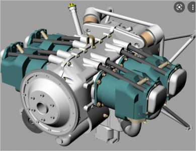
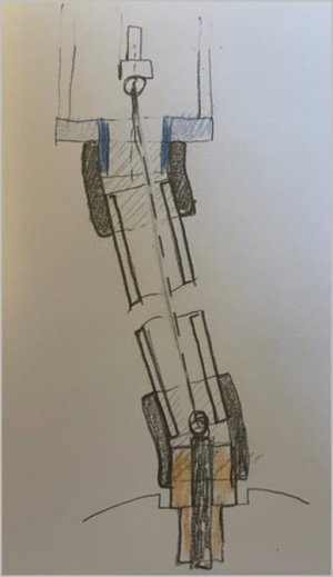
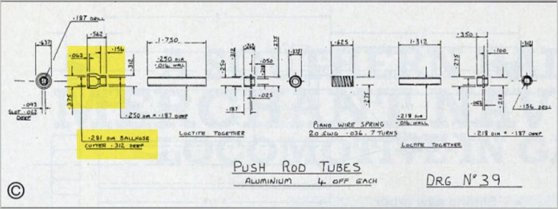
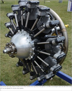
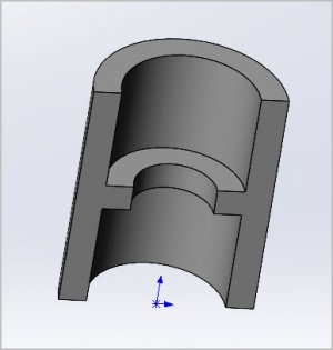
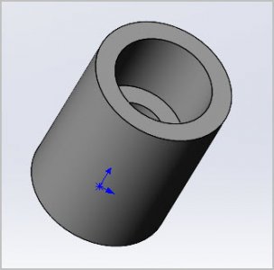
The problem I'm trying to solve on my radial is similar pushrod tubes. The design calls for the tube to overlap the cone shaped tappet bushing at its angle, then a funky 3D hole angle through the bottom of rocker perch held with a teeny set screw. Seems iffy to me on multiple fronts. I would ideally like something rubberized on both ends rather than metal on metal. Dimensionally the tube is only about 0.250" OD x .015" wt x 2" length so kind of finicky small scale.
 

Attachments

  • SNAG-2021-12-18 9.47.37 PM.jpg
    SNAG-2021-12-18 9.47.37 PM.jpg
    37.2 KB · Views: 8
  • SNAG-2021-12-18 9.45.50 PM.jpg
    SNAG-2021-12-18 9.45.50 PM.jpg
    14.1 KB · Views: 10
  • IMG_4141_edited-1.jpg
    IMG_4141_edited-1.jpg
    85 KB · Views: 11
  • EDT-2021-12-18 10.06.26 PM.jpg
    EDT-2021-12-18 10.06.26 PM.jpg
    35.1 KB · Views: 11
  • SNAG-2021-12-18 9.50.21 PM.jpg
    SNAG-2021-12-18 9.50.21 PM.jpg
    90.1 KB · Views: 11

John Conroy

member
Premium Member
The only ones I have experience with are on Harley Davidson engines and the tubes are a 2 piece telescoping type with the pieces held in extension lengthwise with a spring like the tube in a toilet paper holder. The ends are parallel with each other. Ive never seen any where the ends of the tube weren't parallel but since the top and bottom of the tube can rotate independent of each other it would be doable. The spring helps keep pressure on the o-rings through expansion and contraction of heat cycles. This short video shows the construction and assembly method.


CWelkie

Well-Known Member
The pushrod tubes on my Aeronca E-113 uses a spring loaded pushrod tube with o-rings at each end. The tubes are not perpendicular to the head or crankcase entry points. If I remember correctly the corrugated pushrod tubes on a VW flat-4 engine are at an angle as well (the corrugations providing flex and a bit of seal pressure.

Here are some pictures of the Aeronca pushrod tubes and a scan that shows the construction drawing.
DSCN0722.JPG
IMG_7856.JPG
pg27.jpg
 

RobinHood

Ultra Member
Premium Member
The solution to your problem might be a “ball & socket” type joint. If you look at the top ends of these IO-540 tubes, you can see how there would be an appreciable amount of “misalignment” possible as long as the O-ring is flexible enough to still seal.

DC59662D-34E6-4C84-9E2E-121B693BC312.jpeg

Here is another tube system. The exterior spring is what pushes the tube into its seals and allows for thermal movement. The tube ends and seal flanges are not co-axial with the main part of the tube. Intake and exhaust tubes can have different shapes.

A900D3C3-DC2E-4527-945D-1AAB4FBBF510.jpeg
D9D42FD5-4521-4F5D-8481-B9040F853B2A.jpeg
D7DE35F0-E963-403C-806A-F5CE0EA76342.jpeg

Here is a picture of a spring compression tool - they are needed as these springs are quite strong.

E86C8A94-160B-4A5B-9955-ED2F712B1932.jpeg

The link is to the illustrated parts manual of a Lycoming O-360. Both the intake and exhaust tubes are interchangeable. The preload is built into the shroud seal (#19), pg 18-19. There is no external spring.


So I think a combination of spring loaded tube with a socket seal might be the best option.
 

PeterT

Ultra Member
Premium Member
Good resources, thanks guys. It never occurred to me the spring would also related to maintaining seal with temperature change expansion/contraction.

This is hopefully the last bump in the road I need to work through. I like the idea of tubes but I can see now why so many models just run naked pushrods, its much easier. By following the plans & arriving to this point, I've kind of painted myself in the corner now that I see the assembly up close... and don't care for it too much. But its approaching commitment time. I can change the tappet bushings to accommodate something better but ultimately the bushings are permanently bonded in the nose case & I don't want to make another one. The rocker perches are all done but at present undrilled for pushrod/tube entry hole. It would be much easier to drill them obliquely & let a flexible curve seal make up the angle mating. I've figured out jigs to make the requisite 3D angle for tube, but rather a pita. I have some extra perch's so that's where I'm at now, use those as mockup testers to arrive at a solution.

When I was sketching some end seals section profiles & trying to determine how much 3D angle they could accommodate my ideas looked approximately like the FS ones. I have some small, low durometer silicone O-rings but they just don't lend themselves to this kind of assembly. I've been putting off buying some liquid urethane or silicone to cast my own seals from simple aluminum molds, but that capability would give me lots of options for a potential solution & the seals would be identical. There are some other 'rubber' do-dads I need to make on the engine as well so maybe getting up to speed on casting would be worthwhile anyways. I tried bonding a rubber tube on a mandrel, turned in lathe & profiling it with Dremel sanding wheel just to see if it works (kinda but rather crude & uncontrolled). Another thought was to have a cone on either end, nose case & rocker perch underside, but with the cone itself 'rubberized' That might allow a plain jane tubing section to center/seal itself?

Another question on FS rods, I knew they were hollow but I also see a hole on the ball ends. Is oil pressure pumped between tappet & pushrod, or is more of a drain? Or varies by engine? Looking at the VW & O-360 pushrod angles, not appreciably different than mine. But as I've learned many times before, scaling can sometimes be tricky.

Here is a VW post showing the newer style with a bit more closeup of the seal profile.

How To Fit SCAT Pushrod Tubes J27882 & Stainless Steel Rocker Covers J14337 to your air-cooled VW
 

Attachments

  • SNAG-2021-12-19 10.56.04 AM.jpg
    SNAG-2021-12-19 10.56.04 AM.jpg
    205.6 KB · Views: 5
  • SNAGIT.jpg
    SNAGIT.jpg
    64.4 KB · Views: 5

YotaBota

Mike
Premium Member
Could you do something similar to the intake tube setup on the full size aircraft engine. Make nipples for the crank and head, put the tube in between and then use a small diameter hose to join the tube to the nipple? For scale I was thinking vacuum hose or small gas line may be about the right size and the small wire clamps might even work as well.
What is the diameter of the tube?
 

PeterT

Ultra Member
Premium Member
Yes, I think a plain jane section of flexible tubing might actually solve some of the issues at this scale & size. Simple is usually better, or at least a good starting point. (bad sketch). My thinking is the conical bronze lifter bushings would be re-made to a cylindrical profile of ~ same OD as aluminum pushrod tubing. Then have a similar short cylindrical extension coming off the bottom of the rocker perch. Then something like a tight fitting silicone tubing 'sheath' on both ends would overlap these tubing/stub surfaces. I kind of went down this path already with a mockup but maybe dismissed it a bit too soon. I didn't have the right size of silicone tube but I could temporarily fake it with heat shrink or something just to see if the geometry worked. This mode still doesn't prevent metal to metal contact between pushrod tube end if it floats on its own, but maybe he devil is in the details of how I position things. Maybe the flex tubing could be bonded in such a way to prevent this.

The aluminum tube I have is 0.25" OD x 0.015"w.t. But I can machine any kind of end fitting profile & just bond this tubing section to it. or machine a complete tubing with enlarged ends for that matter. Right now the thin tubing wall thickness is not playing nice with an O-ring on end contact. Any little force & the O-ring wants to just slip over or inside the tube because the tube angle is a bit excessive. A geometric 'solution' is where the end part is spherical so the hard tube can sit at any angle & have tangent seal. I suspect that's why those full size rubber end seals have that curved shape. But they are custom molded to purpose. Also the pushrod itself is doing a funky 3D motion inside the stationary tube so I'm going off the plans that the tubing ID will accommodate this clearance wise.

I think I need to roll up my sleeves & mock up one idea at a time complete with pushrods & tubes to physically see what's going on. Often with this stuff, what you perceive as the big issue actually isn't as big a deal, but the new thing that emerges is what you really need to deal with. I am mentally coming close to just running the pushrods naked 'for now' & keep moving towards completion.
 

Attachments

  • SNAG-2021-12-19 12.39.43 PM.jpg
    SNAG-2021-12-19 12.39.43 PM.jpg
    29.1 KB · Views: 5

PeterT

Ultra Member
Premium Member
The pushrod tubes on my Aeronca E-113 uses a spring loaded pushrod tube with o-rings at each end. The tubes are not perpendicular to the head or crankcase entry points. If I remember correctly the corrugated pushrod tubes on a VW flat-4 engine are at an angle as well (the corrugations providing flex and a bit of seal pressure. Here are some pictures of the Aeronca pushrod tubes and a scan that shows the construction drawing.
Nice work!
Maybe I'm misinterpreting the shaded section. Is the ball nose cutter related to seating the tube axis at an angle to the fitting? Or unrelated to this issue & the the angle is taken up entirely by squishing the O-ring slightly different on one side or another?

While I have you, what parts did you harden between the contact surfaces of the assembly: tappet > pushrod end(s) > rocker adjuster socket.
 

Attachments

  • EDT-2021-12-19 12.46.31 PM.jpg
    EDT-2021-12-19 12.46.31 PM.jpg
    64.9 KB · Views: 3

CWelkie

Well-Known Member
The ball nose cutter profile has no bearing on fitment ... it's only there for pretty (and so you can ask about it <grin>). The pushrod tube angle is taken up by the o-ring compressibility.

I didn't harden any of the contact surfaces. If I recall correctly, the rocker adjuster was made from a socket head capscrew (of non-asian origin) and the pushrod itself is of drill rod.

BTW - I think there is at least one R/C four stroke uses the stainless tube / "flexible" tubing end idea for it's pushrod tubes. Without actually looking through my collection I'd guess it's Saito.
 

PeterT

Ultra Member
Premium Member
Yes Saito & OS have a system. I'm not quite sure if they are at a comparable angle. Maybe the O-rings I tried are too hard. May have to revisit that too.
 

Attachments

  • SNAG-2021-12-18 8.44.10 PM.jpg
    SNAG-2021-12-18 8.44.10 PM.jpg
    59.6 KB · Views: 6
  • SNAG-2021-12-18 8.45.11 PM.jpg
    SNAG-2021-12-18 8.45.11 PM.jpg
    27.9 KB · Views: 6
  • SNAG-2021-12-18 8.41.54 PM.jpg
    SNAG-2021-12-18 8.41.54 PM.jpg
    43.9 KB · Views: 6

PeterT

Ultra Member
Premium Member
@CWelkie this was the ball & socket picture I was trying to remember (Technopower radial). A bit bulbous looking but probably functional. Some of the other Technopower variants looked less conspicuous for some reason, maybe slightly different layout? It almost seems like the tube bottom overlaps the tappet bushing profile similar to my conical ones? Been trying to find an online parts manual but no luck so far.
 

Attachments

  • SNAG-2021-12-19 5.54.32 PM.jpg
    SNAG-2021-12-19 5.54.32 PM.jpg
    224.3 KB · Views: 6
  • SNAG-2021-12-19 5.58.10 PM.jpg
    SNAG-2021-12-19 5.58.10 PM.jpg
    64.7 KB · Views: 6
  • SNAG-2021-12-19 5.57.44 PM.jpg
    SNAG-2021-12-19 5.57.44 PM.jpg
    190.7 KB · Views: 6

CWelkie

Well-Known Member
The Technopower solution could be cleaned up if half-spheres were used. With the little bit of oil involved they might seal well enough. Certainly the lowest parts count. Glow engines seem to run in a "fog of oil" anyway so a little leakage just indicates that oil is getting there ...

I've never been a fan of the "flexible tube on a solid tube" connection - they look kludgy and the flexible tube gets stiff and brittle. Just a cheap afterthought.

Another solution would be to copy Enya's tubes with rolled bead flanges on the top end and o-rings. One could make a bead roller or solder rings to the tubing.
 

PeterT

Ultra Member
Premium Member
Just a quick update. Well I've been itching to try silicone casting for other reasons. But I wanted to explore if it could solve my pushrod coupler issue. Unfortunately its a rather fussy shape. The coupler ID = 0.250, wall thickness 0.050", length = 0.300". It also has 0.050" thick internal step mid length to act as an internal stop for the aluminum tubing ends, kind of like a captive O-ring. The general idea is ideally I would have a standard part to marry the upper top end (axially to a tube segment coming from the rocker box) and the lower tube end (at a funky 3D angle to the tappet bushing).

In terms of the general casting aspects, it went pretty well for a first try. I was concerned about mixing tiny volumes of A&B at 10:1 ratio. Then adding pigment to some other max %. The molds are 3-part affair to get the shape, rather a pita at this scale but everything released properly. Entrained bubbles are a big issue & I only have one way to pour conveniently, but there weren't any visible defects. This is Smooth-On brand 29 durometer NV (= no vacuum) which basically means its a thinner pour viscosity than silicone of similar durometer.

Anyways, I'm not thrilled by the end result, but I have to start somewhere. It looks very fat which I was expecting. But that means thinner walls are required, or maybe cast it undersize & count on some elastic stretch which wouldn't be a bad thing judging by my trial with plain silicone tubing. There are flexible/moldy things I want to make so it justified buying the material for experimenting. Older gen real radials have a more elegant mechanical coupler which is very difficult to scale. Although I stumbled on a modern Rotec that looks conspicuously similar.

So if you have some application like an unobtanium odd shaped rubber boot that needs to be replaced, this silicone method might be a solution.
 

Attachments

  • IMG_4270_edited-1.jpg
    IMG_4270_edited-1.jpg
    75.1 KB · Views: 5
  • SNAG-2022-01-22 9.44.40 PM.jpg
    SNAG-2022-01-22 9.44.40 PM.jpg
    65.4 KB · Views: 4
  • SNAG-2022-01-22 9.44.29 PM.jpg
    SNAG-2022-01-22 9.44.29 PM.jpg
    44.4 KB · Views: 4
  • SNAG-2022-01-22 9.43.54 PM.jpg
    SNAG-2022-01-22 9.43.54 PM.jpg
    75.7 KB · Views: 4
  • SNAG-2022-01-22 9.14.56 PM.jpg
    SNAG-2022-01-22 9.14.56 PM.jpg
    299.3 KB · Views: 4
  • SNAG-2022-01-17 10.47.07 PM.jpg
    SNAG-2022-01-17 10.47.07 PM.jpg
    18.2 KB · Views: 5
  • SNAG-2022-01-17 10.46.27 PM.jpg
    SNAG-2022-01-17 10.46.27 PM.jpg
    14.2 KB · Views: 4
  • IMG_4282_edited-1.jpg
    IMG_4282_edited-1.jpg
    116.7 KB · Views: 4
  • IMG_4269_edited-1.jpg
    IMG_4269_edited-1.jpg
    61 KB · Views: 4
  • IMG_4265_edited-1.jpg
    IMG_4265_edited-1.jpg
    74.7 KB · Views: 4
The flex section on some pipes are to allow for thermal expansion and contraction (difference of materials along with heat transfer) basically it allowed the tightest fit without having to consider sliding tubes.
 

PeterT

Ultra Member
Premium Member
Yes there's that thermal aspect too for sure. Although my model tubes are short ~2" length, so hot/cold thermal deviation will probably be pretty small. The external tube boot appears to accommodate thermal & 3D geometry & vibration issues simultaneously. They look kind of crude but seem to do the job. I just have nuisance residual oil, not pumped lubrication oil. Although I'm not sure yet if/how to scale those clamps. I have to address that on the induction tube side as well. These details have sucked time chasing blind alleys but I guess that's part of the fun.
 

PeterT

Ultra Member
Premium Member
I take it that 3D printing flexible rubbery things is kind of at an early stage? Has anyone done work like this on their own machines?

 
One of the labs I did during Civil Engineering was a Thermal Expansion using Aluminum, Steel, wood, glass rod, cooling with ice and heating with steam, you'd be surprised at the large variations even for small distances.

Help my daughter do this as a simplified Science Fair demonstration when she was 8 or 9. Even with low temperature variations it is measurable (cooled and hot tap water) over a 7.5 inch length.
 

PeterT

Ultra Member
Premium Member
Yes I was curious myself. The pushrod tubes bridge between the crankcase & rocker boxes which are mounted on head. They receive full blast of propeller air so not sure what the average temp would be. The head is ~275F so even if the whole tube was at that level, which is hard to imagine - subtract ambient, call it 200F delta. Not sure if I have the right formula, chart shows ~3 in/100 ft expansion, so over 2" length yields 0.005" growth. The silicon couplers should handle that. But yes, on metal to metal fits, teeny changes can have bigger impact.
 

Attachments

  • SNAG-2022-01-25 7.45.53 PM.jpg
    SNAG-2022-01-25 7.45.53 PM.jpg
    60.1 KB · Views: 1
Top