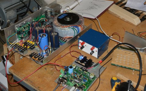
When I was using DC servos with a massive 1500W, 105VDC power supply. The two small boards on the side of the assembly are custom projects, one with a PIC processsor. In order to prevent that massive startup current surge the system enables a relay that puts a resistor in series with the 220VAC input to the transformer. This limits the startup current much like the older varistors in Tube Televisions a long time ago. Except it doesn't stay and remain hot then being useless for a power cycle.
Once the time delay is complete full power goes to the transformer and a signal goes to the PC that Servo Power is now available.

The other little board in the power supply does two things. If the voltage goes above a certain amount, which happens as DC Servos decelerate and turn in to generators, or when AC power is removed a load resistor is put across the power supply to get rid of the voltage above 105VDC or all of it quickly when powered down. That's for safety so I don't electrocute myself.
In the bottom corner of the photo is the HP_UHU servo drive kit and above that ELS #1 used to provide the step/dir for testing the motor.
The STMBL AC Servo also used the 105V even though the motor is rated at a much higher voltage since this was easier. The problem I ran into was that once the system was enabled the 'ENABLE' signal was sent out to all drives. However since the DC voltage was still rising, the STBML would create a 'FAULT' which would then shut down the 'ENABLE'. And this would cycle. Very annoying.
The PMDX-126 (and the 125 on my MACH3 router) also handle the concept of a Charge Pump. If the PC goes bye-bye the charge pump signal does too and that immediately results in a shutdown of all AC and DC power to things that could be moving. Not an issue for stepper motors but can be for other hardware.
I don't think the simpler systems handle Charge Pump signals.
Once the time delay is complete full power goes to the transformer and a signal goes to the PC that Servo Power is now available.

The other little board in the power supply does two things. If the voltage goes above a certain amount, which happens as DC Servos decelerate and turn in to generators, or when AC power is removed a load resistor is put across the power supply to get rid of the voltage above 105VDC or all of it quickly when powered down. That's for safety so I don't electrocute myself.
In the bottom corner of the photo is the HP_UHU servo drive kit and above that ELS #1 used to provide the step/dir for testing the motor.
The STMBL AC Servo also used the 105V even though the motor is rated at a much higher voltage since this was easier. The problem I ran into was that once the system was enabled the 'ENABLE' signal was sent out to all drives. However since the DC voltage was still rising, the STBML would create a 'FAULT' which would then shut down the 'ENABLE'. And this would cycle. Very annoying.
The PMDX-126 (and the 125 on my MACH3 router) also handle the concept of a Charge Pump. If the PC goes bye-bye the charge pump signal does too and that immediately results in a shutdown of all AC and DC power to things that could be moving. Not an issue for stepper motors but can be for other hardware.
I don't think the simpler systems handle Charge Pump signals.
