• Scam Alert. Members are reminded to NOT send money to buy anything. Don't buy things remote and have it shipped - go get it yourself, pay in person, and take your equipment with you. Scammers have burned people on this forum. Urgency, secrecy, excuses, selling for friend, newish members, FUD, are RED FLAGS. A video conference call is not adequate assurance. Face to face interactions are required. Please report suspicions to the forum admins. Stay Safe - anyone can get scammed.

PM Models #5 steam engine

phaxtris

(Ryan)
Premium Member
Premium Member
Lets pile on one more project! The box for this little guy has been staring at me from under the mill for almost 2 years now (i bought it the same time i bought the #1 model engine kit), i figured with work being slow i should check things off the list, and this guy being already paid for AND having all of the tooling from the last steam engine would make a perfect candidate, its also giving me a break from the airplane and its associated spending


This one has a few different challenges that were not in the #1, it should keep me busy for a little while

IMG_20250211_174908324[1].jpg

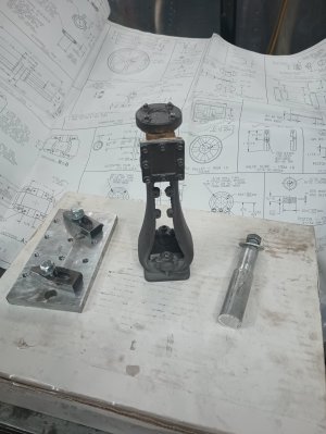
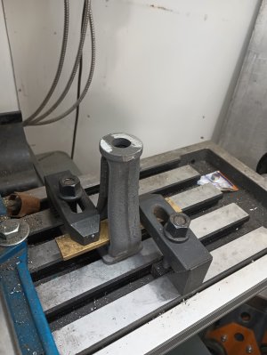
Ive started with the main frame of the engine. Trying to get a reference surface to work from with casing is a bit tricky, nothing is flat, square or straight, first thing i did was file/sand the bottom of the coke bottle somewhat flat, put it on the mill with a square, and measure the top from 4 sides, trying to get it as plumb as possible. Once i was satisfied that it was about as plumb as it was ever going to be it was time to clamp it to the table and mill the area where the cylinder will mount, taking off as little as possible, this is just a reference/square surface to work from.
IMG_20250211_163247618.jpg

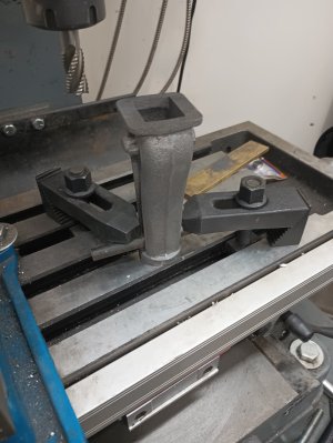
After milling off the top, it was time to flip it over, this was not a great setup, i had to take many small shallow cuts to avoid it chattering all over the place
IMG_20250211_164455751.jpg

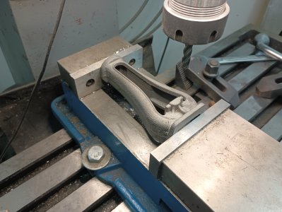
finally with two square parallel faces i was able to put it in the vise (barely) and clean up/mill to dimension the bearing faces
IMG_20250211_171756023.jpg

Flip over, clean up the cross slide support bosses, drill, and tap the 4 2-56 threaded holes....im amazed i haven't broken one of these 2-56 taps yet
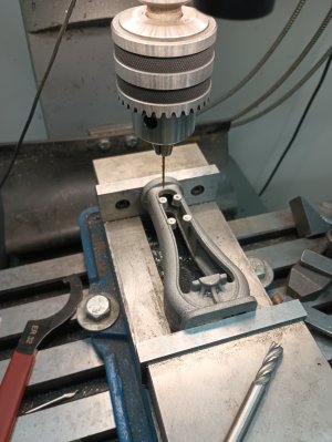
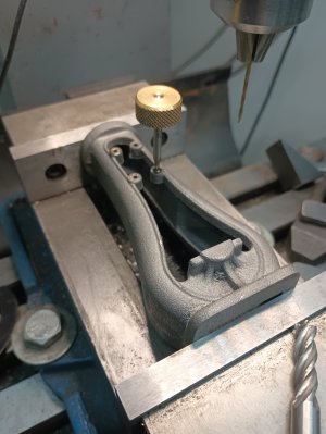
IMG_20250211_174016688.jpgIMG_20250211_174637947.jpg

Thats it for tonight.
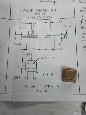
 
Nice start.

Getting ahold of these parts, and finding that reference surface, seem to be the hardest part!
 
I have the same kit, about 2 years old as well... Still in the box. How do you plan to drill the main bearing cap holes? When I first looked I thought machining a block with holes as a drill guide would be best. It needs a long drill to reach

1000011776.png
 
Nice start.

Getting ahold of these parts, and finding that reference surface, seem to be the hardest part!

I would agree, definitely some thought and acceptance of slight visual imperfections need to be made to get started

Another cool project. I envy your productivity.

thanks, i try, some times you tube does get the better of me and nothing gets done! lol

I have the same kit, about 2 years old as well... Still in the box. How do you plan to drill the main bearing cap holes? When I first looked I thought machining a block with holes as a drill guide would be best. It needs a long drill to reachView attachment 59670

Ive thought about making a drill extension, but with a quick look it doesnt look like there is enough clearance. Ive also been thinking of drilling through the base, a normal drill bit would be long enough, its just a matter of locating the holes. I think its a feature that didnt scale well to the model, and no one put much thought to it. What ever plan i go with there will be pictures of the outcome
 
Sorry, I don't know much about these kinds of model engines. I did a search & was kind of surprised there weren't a bunch of active builds on the forums I frequent. Maybe you are familiar already but this channel has what looks to be relatively recent (but early stage) vids in progress


Attachments

  • 1739401181120.png
    1739401181120.png
    117.7 KB · Views: 3
after a short day at work and some v day preparations i managed to get a little more progress

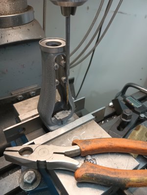
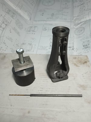
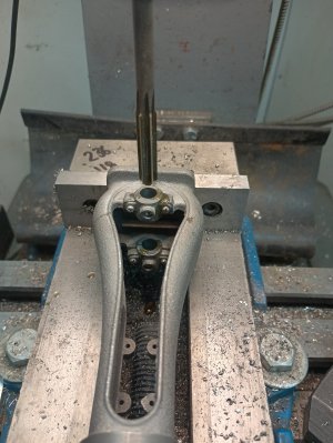
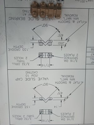
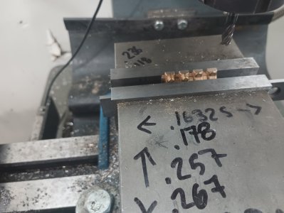
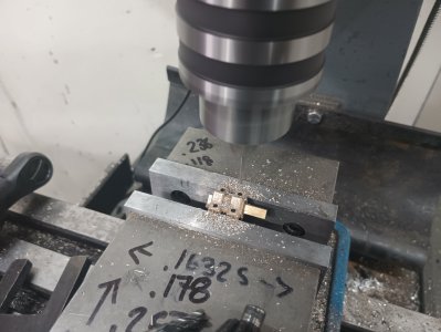
If you add up the math for the bearing cap hold down holes there is just enough room to sneak a 3/16 rod down from the top, in a perfect world anyhow, i did have to file a little bit of the casting, and widen the bolt pattern by 20 thousands, tapping was another story, there is 0 room to get a tap handle of any kind in there, i held the tap with my fingers and turned the tap with a pair of vise grips with the whole arrangement in my lap

@ShawnR the hole size called is a #50 (.070) for a 2-56 screw, unfortunately to small for those long bits

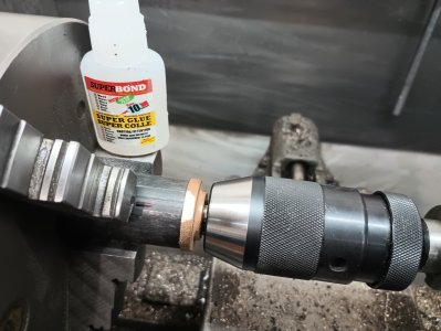
it was a pretty simple operation to make an extension, chucked up a piece of 3/16, drilled it out with the bit, then crazy glued the same bit in the hole (the picture is the second crazy gluing....didnt quite get it in before the glue setup)

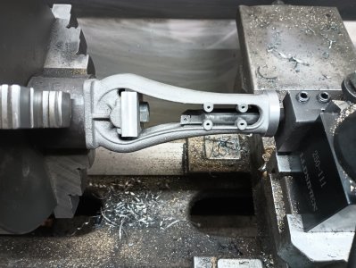
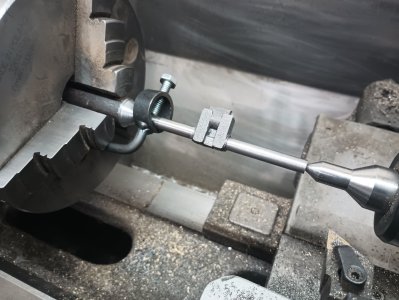
there is also a picture of the little fixture i made to hold the bottle in the lathe, it worked out alright, with some slight chatter

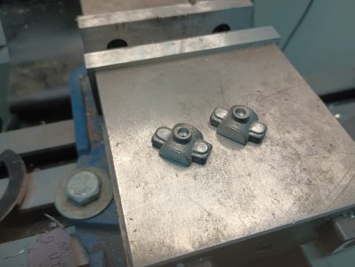
the bearing cap castings are not the greatest match to the base, after drilling/tapping and mounting the caps, i glued them in place and ground the ?ears? of the caps to match the base casting, followed up by a quick sandblast to hide the grinding marks

IMG_20250212_153632940.jpgIMG_20250212_192216273.jpgIMG_20250212_165402851.jpgIMG_20250212_200829229.jpg

@PeterT i haven't seen that guys videos before, but there are several youtubers that build the various kits, but your right, not a whole lot of guys that do the steam engine castings, i think there is more interest in building ICE engines.....a lot more difficulty in that!
 
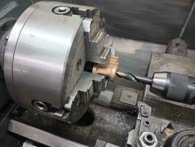
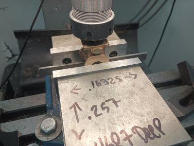
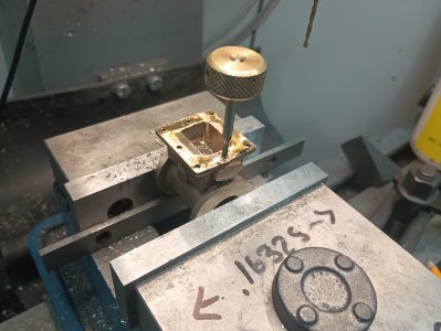
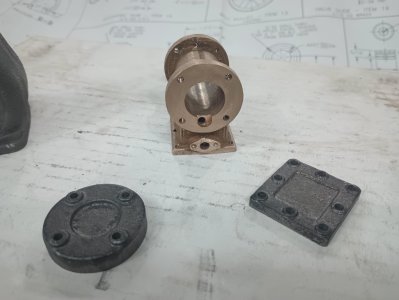
Tackled the cylinder today, it has by far the most processes and setups, i wasn't very good with the photos today, only 2 shop made items to complete this, a mandrel and small fixture board

using a drill bit in the tailstock to roughly center the cylinder for boring in the 4j

IMG_20250213_083926182.jpg

you really have to trust the DRO and your math with the ports, you cannot see anything, the center port was made with a 3mm cutter, and the outboard ports are made with a 2.5mm cutter

IMG_20250213_111954350.jpg

More tiny little 2-56 threaded holes

IMG_20250213_114136962.jpg

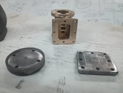
cylinder, cylinder head, and valve chest cover, the little hole you see in the cylinder bore intersects with the outer ports at a 20deg angle, there is one of those ports in each end of the cylinder

IMG_20250213_155549221.jpgIMG_20250213_155602061.jpg

Its always a good feeing when all the bolt holes line up

IMG_20250213_155138717.jpg
 
you really have to trust the DRO and your math with the ports, you cannot see anything, the center port was made with a 3mm cutter, and the outboard ports are made with a 2.5mm cutter
Christmas is coming LOL
 

Attachments

  • EDT-13-02-2025 4.13.59 PM.jpg
    EDT-13-02-2025 4.13.59 PM.jpg
    100.5 KB · Views: 2
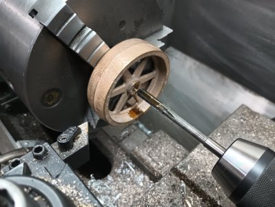
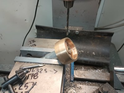
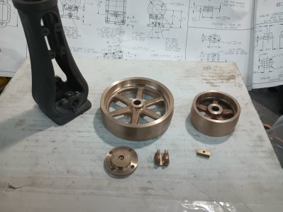
Couple more bits and bobs, unfortunately boring the bearing caps didnt go perfectly, a little off center, i will just have to live with that mistake. Everything else went swimmingly

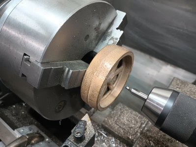
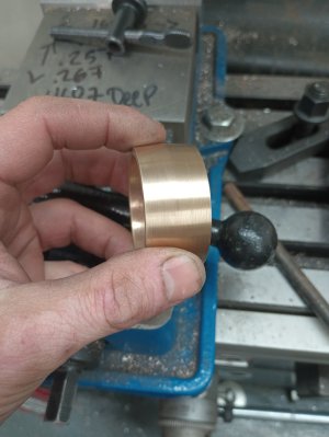
I didnt notice until uploading the photos, i think i may turn the od of that smaller pulley a few more thousands, seems there is a little bit of casting showing

IMG_20250214_101047585.jpgIMG_20250214_111840350.jpgIMG_20250214_180344532_HDR.jpgIMG_20250214_180841440.jpgIMG_20250214_181049259.jpgIMG_20250214_185951633.jpgIMG_20250214_192848751.jpgIMG_20250214_193807444.jpg
 
Last edited:
Love those flywheels. Coming together nicely.

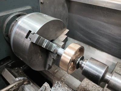
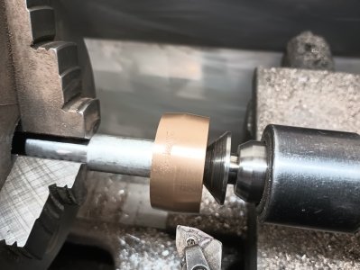
Is that cone center shop made? Looks handy.

The solid brass sure does look pretty doesn't it

That center came with the lathe, i believe they are called "bullnose center's".....i assume its for pipe/tube work
 
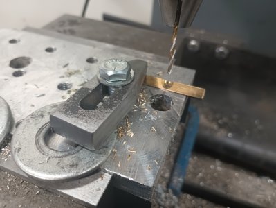
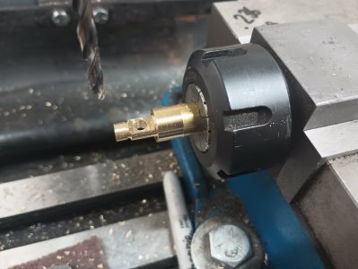
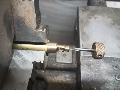
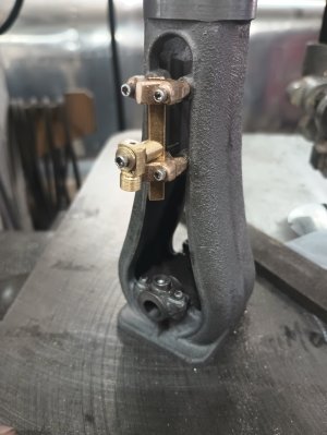
a few more bits completed today


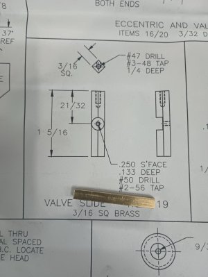
also started on the crank, trying to center drill the one end i found a hard spot, burned up 2 center drills before i decided to just hack 1/4" off and try again, that worked. turned both main journals between centers and polished to .3125, fits perfect in the reamed .313 main caps, yey! Haven't completed the throw yet, i will need to make some kind of fixture for that, its to small to simply offset in the 4j


IMG_20250219_101117243.jpgIMG_20250219_101559121.jpgIMG_20250219_111806834.jpgIMG_20250219_114712114.jpgIMG_20250219_120225922.jpgIMG_20250219_141129978.jpgIMG_20250219_141736815.jpgIMG_20250219_143210344.jpg
IMG_20250219_150434188.jpg
 
Last edited:
Did you see Blondihacks jig for turning the crank? I built one for my Stuart 10V and it works well.
The jig making starts at about 10 minutes.
 
Back
Top