Offset and crooked lead screw nut

slow-poke

Ultra Member
Well I made a little discovery on the A1S mill just now, hope others can comment on what I discovered.

This relates to this thread, but I don't want to sidetrack that thread so I'm starting a new one.

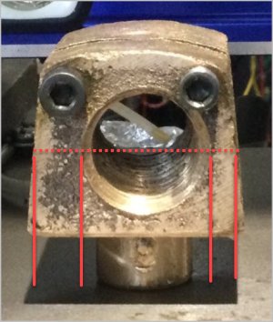
I'm attempting to take fairly accurate measurements of the X axis saddle particularly around the leadscrew nut because a 20mm balllscrew upgrade is going to be very tight.

I'm not sure if what I found is just the way these are manufactured or if this is particularly sloppy. I would expect the bronze nut to be placed more or less perfectly centered. Clearly the mounting hole for the nut is offset by about 5mm to the right. Further the threaded hole in the bronze nut is further offset to the right by about another 3mm!

My first thought was that they goofed when they drilled the hole in the saddle and offset the hole in the nut to compensate, except the offset in the nut is in the wrong direction, second thought was they goofed again and put the nut on backwards, so I flipped it around to see if it partially corrected the offset, no almost the same, under closer examination the hole through the nut is quite angled to compensate for the offset.

So my best guess is they just bolt the nut on there any which way and then drill and tap it in place probably with some sort of jig fixed on the end cap.

Seems sloppy?

Comments please.
DD00C051-2112-4B19-B332-40EBF5BB12A0.jpeg 08C36CA7-92EB-49E1-9B2B-E07CD8EFFEFD.jpeg E59356CA-B1F8-4E88-925B-754F70353CFA.jpeg
 

PeterT

Ultra Member
Premium Member
Yes I think perfectly centered is what is required. Whatever fixturing they assumed they could count on obviously failed. My 14x40 lathe leadscrew was somewhat similar factory fart. It was bowing to comply with incorrectly positioned bracket to engage it to the worm gear inside the saddle & caused me lots of grief. Check your leadscrew, it may be bent as a result. Even if you are no longer using it yourself, but for someone else's sanity down the line. If your table end fittings are more or less dictating the leadscrew position, then I'd figure out a way to work around the existing nut hole if you plan on using it. Maybe its just an anchor spot for a more laterally adjustable nut fixture if the casting hole is too difficult to drill out. Or if you are going to ball screw nut it gets bypassed anyways? Your ABL nut might be worn in a weird way now as well. Its unfortunate but typical - they go through all that work to build a machine & then screw up THE most critical thing with oversight.
 
Honestly, don't over think it. If it works it works. Over thinking things gets individuals in more trouble than anything else.

If you are installing ballscrews, mount them where it works best for your application. Other than that who cares.
 

slow-poke

Ultra Member
Honestly, don't over think it. If it works it works. Over thinking things gets individuals in more trouble than anything else.

If you are installing ballscrews, mount them where it works best for your application. Other than that who cares.

Good point:

+ Travel was smooth and the table was quite tight.
+ Upon further examination, I now realize that the ways are wider on the RHS, so my offset measurements are bogus. Plan of the day is to 3D print the mounting block I envision and then see if it looks reasonable if not tweak and reprint, when I'm happy make the actual mounting block.

Any reason I should not make the mounting block out of aluminum?

I will probably make a drill jig that fits in the end bearing to find center for the final mounting block.
 
My mounting block for the will be Steel to allow maximum clearance for mounting. Bearing blocks at when of table and cross slide will be Aluminium.

For the table is will be place and mount nut where desired bearing blocks manufactures to suit.
 

PeterT

Ultra Member
Premium Member
When you say 'travel was smooth & table was tight' what do you mean? If you're sliding the table with gib strip in but no leadscrew just to assess smooth travel through the range prior to ball screw conversion, that's fine. But its only part of the story without leadscrew & nut within the assembly. What I'm getting at is verifying your leadscrew orientation just to be confident that its parallel to your (dovetail) ways which is typically dictated by the table end castings. If it happens to be out of alignment for whatever reason, you are just transferring the problem to a less tolerant (ballscrew) system.

The reason I mention is: maybe optical illusion but your existing ABL nut does not look centered. if so, it could be the table hole was drilled offset to leadscrew. But could also be the leadscrew is misaligned. Personally I would measure. You didn't mention this but FWIW is not an uncommon issue: 'my table feels good in the mid range but gets increasingly tight at either end'. Retrofitting to a ballscrew system doesn't magically fix a geometry problem. If none of this pertains to your situation, that's fine. Its just a whole lot easier to do some basic checking now. Of course, its your machine & you are welcome to accept or ignore advice from whomever.
 

Attachments

  • EDT-14-11-2023 4.32.29 PM.jpg
    EDT-14-11-2023 4.32.29 PM.jpg
    52.3 KB · Views: 1

slow-poke

Ultra Member
When you say 'travel was smooth & table was tight' what do you mean? If you're sliding the table with gib strip in but no leadscrew just to assess smooth travel through the range prior to ball screw conversion, that's fine. But its only part of the story without leadscrew & nut within the assembly. What I'm getting at is verifying your leadscrew orientation just to be confident that its parallel to your (dovetail) ways which is typically dictated by the table end castings. If it happens to be out of alignment for whatever reason, you are just transferring the problem to a less tolerant (ballscrew) system.

The reason I mention is: maybe optical illusion but your existing ABL nut does not look centered. if so, it could be the table hole was drilled offset to leadscrew. But could also be the leadscrew is misaligned. Personally I would measure. You didn't mention this but FWIW is not an uncommon issue: 'my table feels good in the mid range but gets increasingly tight at either end'. Retrofitting to a ballscrew system doesn't magically fix a geometry problem. If none of this pertains to your situation, that's fine. Its just a whole lot easier to do some basic checking now. Of course, its your machine & you are welcome to accept or ignore advice from whomever.

Table feels great with the leadscrew installed cranking from end to end with no perceived increased resistance at ends, when I say tight I just mean the table is tights as in with the gibs adjusted so there is no play in the table.

My best guess re the offset in the factory nut is, they just bolt the nut on there any which way and then drill and tap it in place probably with some sort of jig fixed on the end cap(s) to eliminate the alignment errors that are likely to occur if they machine the various parts in isolation and then assume everything will line up when they are assembled. So what I perceive as sloppy manufacturing is probably just a sensible way to manufacturer this by eliminating the accumulated errors, by drilling and threading the nut in its actual location.

Assuming my hunch is correct, it does make positioning a mounting block for a ballscrew a bit more tricky, I will probably make a jig to find the center of the new mounting block, seems like the most accurate way to get the new block lined up.

Thanks.
 
Last edited:
Top