I was talking to Matt at Precision Matthews a few weeks back asking some questions about a power feed for the knee on my mill. I have a bum shoulder and cranking the knee up and down by hand is a pain, literally. He told me there are 2 different models, one for machines with 3/4" by 16 TPI SAE thread on the knee lead screw and the others have a 19 mm X 1.5 mm metric thread. I checked mine carefully with thread pitch gauges and found it to be the SAE thread. He offered me a great deal and I ordered one as an early Christmas gift to myself.
It arrived a few days later and I got to work installing it on the weekend. It comes with an extension shaft for the lead screw to add the extra length need for the drive unit plus all the other hardware required. The instructions are the usual chinglish so I did some research online before starting. This unit is made in Taiwan by the same company that made the Align brand power feed that's on the X axis of my mill. That one has been trouble free and all the hardware looks to be top quality so I'm confident this thing will last.

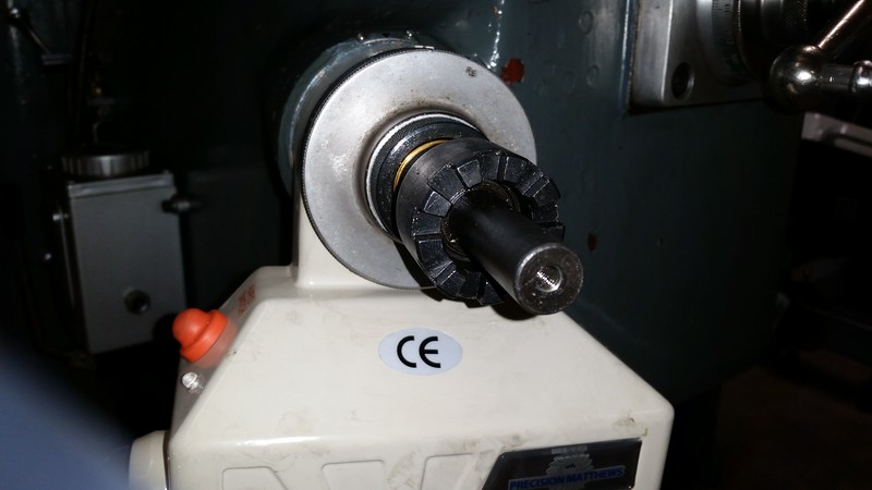
I started by removing the original drive clutch, it is keyed to the shaft and just slides off.

Then the micrometer dial and it's lock nut.


The hub that the dial rides on is threaded onto the 3/4" X 16 TPI threads on the shaft. It is these threads that determine which model to order and where the extension shaft in the kit will thread onto.

Then the bearing retaining plate. As you can see, on my mill it is held on by 3 hex head bolts. There would normally be recessed socket head cap screws here but the plate was damaged when I got the machine so I used the hex heads instead. The good news it the kit comes with a new plate.


At this point the lead shaft can just be pulled straight out with the 2 bearings still attached.


The new extension shaft will now be what holds the outer bearing into it's support so it must be threaded completely on until it sits against the inner race of the bearing, then pinned in place so it doesn't simply back off when turning the shaft counter clockwise.


I put the whole shaft in the vise and used a wrench to tighten the extension shaft firmly against the bearing. Then I levelled the flats and drilled a 3/16" hole for a roll pin.


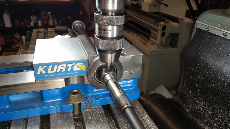

Of course I had to make sure the table was at the correct height for drilling before I removed the shaft. It was sheer luck that it was at the correct height.
Then I reinstalled the shaft with the new bearing retaining plate which has the 2 mounting holes for the drive unit. You can orient the unit in 3 different positions but I wanted it to be vertical.

When it was mounted like this I had a small amount of interference between the drive unit body and the knee. I removed a little material from the knee with an angle grinder to provide a little clearance.


John
It arrived a few days later and I got to work installing it on the weekend. It comes with an extension shaft for the lead screw to add the extra length need for the drive unit plus all the other hardware required. The instructions are the usual chinglish so I did some research online before starting. This unit is made in Taiwan by the same company that made the Align brand power feed that's on the X axis of my mill. That one has been trouble free and all the hardware looks to be top quality so I'm confident this thing will last.
I started by removing the original drive clutch, it is keyed to the shaft and just slides off.
Then the micrometer dial and it's lock nut.
The hub that the dial rides on is threaded onto the 3/4" X 16 TPI threads on the shaft. It is these threads that determine which model to order and where the extension shaft in the kit will thread onto.
Then the bearing retaining plate. As you can see, on my mill it is held on by 3 hex head bolts. There would normally be recessed socket head cap screws here but the plate was damaged when I got the machine so I used the hex heads instead. The good news it the kit comes with a new plate.
At this point the lead shaft can just be pulled straight out with the 2 bearings still attached.
The new extension shaft will now be what holds the outer bearing into it's support so it must be threaded completely on until it sits against the inner race of the bearing, then pinned in place so it doesn't simply back off when turning the shaft counter clockwise.
I put the whole shaft in the vise and used a wrench to tighten the extension shaft firmly against the bearing. Then I levelled the flats and drilled a 3/16" hole for a roll pin.
Of course I had to make sure the table was at the correct height for drilling before I removed the shaft. It was sheer luck that it was at the correct height.
Then I reinstalled the shaft with the new bearing retaining plate which has the 2 mounting holes for the drive unit. You can orient the unit in 3 different positions but I wanted it to be vertical.
When it was mounted like this I had a small amount of interference between the drive unit body and the knee. I removed a little material from the knee with an angle grinder to provide a little clearance.
John
Last edited: