• Scam Alert. Members are reminded to NOT send money to buy anything. Don't buy things remote and have it shipped - go get it yourself, pay in person, and take your equipment with you. Scammers have burned people on this forum. Urgency, secrecy, excuses, selling for friend, newish members, FUD, are RED FLAGS. A video conference call is not adequate assurance. Face to face interactions are required. Please report suspicions to the forum admins. Stay Safe - anyone can get scammed.

New to me Bridgeport Mill

Susquatch

Ultra Member
Administrator
Moderator
Premium Member
Just acquired a new to me Bridgeport Mill. I do not have access to 3ph power - only 110/220 so I can't actually run the machine yet.

Here is a quick link to the original thread about finding a good mill.

https://canadianhobbymetalworkers.com/threads/where-to-get-good-used-mill.3372/

Here is a link to the Hartford mill I acquired at the same time.

https://canadianhobbymetalworkers.com/threads/new-to-me-hartford-mill.3490/

Here is a quick survey of the mill and its condition as received:

Bridgeport Textron
Series I - 2Hp
US Electric Motors 575
Rewound by Morrish
(morrishemco.com) to 430V
Serial Number J221566
Drive Serial Number 2J 88733/2
Gross weight approximately 2000 pounds

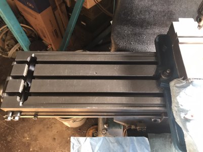
Bed is rusty and badly hen pecked
Needs to be scraped
90 thou x-axis over length
105 thou y-axis over length
Oil pump plunger sticks when pulled up
Y slides good condition ways and Gibbs good
X slides good condition ways and gibbs good
Z slides good condition

Left Side
Head too far forward.
Broken left side handle
Missing pull knob
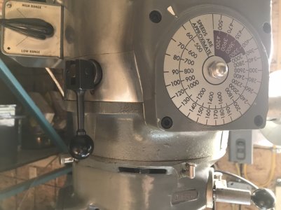
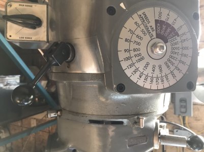
What is cam lock left of speed
adjust for?
Spindle brake? Won't lock
Speed adjust seems
WAY too loose

Right side
Missing original Quill arm
(has homemade one)
Missing Base Pillar lock arm
Power Quill Feed seems ok
Speed Range
can't keep it in neutral

Front
Quill manual wheel missing
Table Lift lever ok
Table lift lock arm broken off
No way to clamp R8 tools
to tighten draw bar

Spindle
Rotates freely and smoothly
R8 key pin Missing
Can't lock Spindle
to tighten drawbar

Bridgeport Left.jpg
Bridgeport Bed.jpg
Bridgeport leadscrew.jpg
Bridgeport Head Left.jpg
Bridgeport Head Front.jpg
Bridgeport Drive Front.jpg
Bridgeport Ways.jpg
Bridgeport Head Left2.jpg
Bridgeport Crank Left.jpg
Bridgeport Table Front.jpg
Bridgeport Crank Right.jpg
Bridgeport Right.jpg
Bridgeport Head Right.jpg
Bridgeport Base Right.jpg
 
Last edited:
Here is the Bridgeport after lifting it a few inches and then driving my flatbed out from under it.

My little loader tractor that can!!!

She is a beast of a tractor and always has been from the day I got it. Outpulls and outlifts many tractors two sizes bigger.

I admit that she even surprised me on this one. She squatted a bit as she took up the load and nothing happened. I thought it was over. Then just as quickly, the mill just lifted up off the flatbed as though it was made of foam.

20210605_175332.jpg


OH ya, in case you are wondering, the rear tires have liquid ballast in them. If that had been too little, I would have filled the sprayer tank with water.
 
Keith Fenner is doing a video series on a Bridgeport rebuild he calls 'Buffy' just for interest sake. Likely different model, but sometimes helps to see the innards from different peoples perspective.
 
Keith Fenner is doing a video series on a Bridgeport rebuild he calls 'Buffy' just for interest sake. Likely different model, but sometimes helps to see the innards from different peoples perspective.

Thank you!

I don't know who Keith Fenner is, but I do enjoy watching videos about stuff like that and I confess I've learned a lot that way!

I'll see if I can find them.
 
@Susquatch : the top of that Bridgeport is not correct for a variable speed machine - that is the brake and lock assembly for a step drive Bridgeport.

I am thinking that the machine has been adapted from the variable drive to the step drive and then the owner would speed control with a VFD. Not a deal breaker by any means.


Both your Harford and the Bridge ports all have the same features - same mills, different names as near as I can tell - parts should be interchangeable

My mistake. Good catch. That top of the drive photo is the Hartford. That's what I get for bulk photo inserts.

I deleted that photo here and will add it to the Hartford shortly.

Here is the top of the Bridgeport.

20210606_184011.jpg
 
@Susquatch : I attached the parts section for the variable speed head.

What can happen is that if someone dials up and down the speed without the spindle turning, the pulley plates come apart and pinch the belt such that is gets stuck at speed. You can then dial up and down the speed control as it is doing nothing.

You can try putting the spindle in high and rotating it clock wise - if the belt follows the pulleys it will gradually get stiffer to turn - not overly stiff though and the speed lever will tighten up as the belt comes into the position it should be at. You can check on things through the front if you remove the speed adjust - it should stay connected by the chain to the swash plate- see where the belt is positioned. The odd time the pulley plates will stick if the key ways are worn - these are teflon material coated and replaceable - helps the pulley move up and down.

Usually I have my mill repair book on board but it is home...alas...or I could send you some scans
 

Attachments

@Susquatch : I attached the parts section for the variable speed head.

What can happen is that if someone dials up and down the speed without the spindle turning, the pulley plates come apart and pinch the belt such that is gets stuck at speed. You can then dial up and down the speed control as it is doing nothing.

You can try putting the spindle in high and rotating it clock wise - if the belt follows the pulleys it will gradually get stiffer to turn - not overly stiff though and the speed lever will tighten up as the belt comes into the position it should be at. You can check on things through the front if you remove the speed adjust - it should stay connected by the chain to the swash plate- see where the belt is positioned. The odd time the pulley plates will stick if the key ways are worn - these are teflon material coated and replaceable - helps the pulley move up and down.

Usually I have my mill repair book on board but it is home...alas...or I could send you some scans

Thanks again for the parts pages for this one too!

I tried turning the Spindle like you described. I assume clockwise is looking at the collet end. Anyway, it's way too difficult to turn. I'll have to fix the collet keyway pin first so I can put a crank or something in a collet to turn the Spindle with.
 
Too
This will set you up - all the repair video you may require on this site


Too funny. My bride and I figured it out on our own. Glad I didn't watch the YouTube video first. No need to tap that Spindle in and out like that. You can get at both Screws with it right where it is with a ball end Allen.

I got the lock screw out easily. But I didn't know the pin was part of yet another screw so we spent quite a bit of time trying to push what we thought was the broken off tip out of the hole. Then my 5ft bride saw the Allen hole in the second screw from down under it.

The 6'3" hairy guy had to get on his knees to see it. But the rest was easy.

On the flip side, it is too bad I didn't see the video first. I never thought to index the Spindle collar.... But it has a recess to take the lock screw so it will be easy to get it right.

I'll have to buy or make one of those pins.

I subscribed to the channel.

Thanks Brent!
 
430V is a good thing: take a VFD connect it to 220V and a 3 phase 1:2 step-up transformer to the motor - done.

What makes you think you need to re-scrape the table? I bet if you use some rust remover, some WD-40 with a fine scotchbrite pad and a bunch of elbow grease, that table will be just fine.

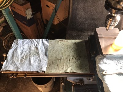
The pecker tracks: stone off the ridges to make sure there is nothing above the table surface and be done with them. If you don’t like the looks of them, put table covers on either side of the vise and no one will know they are there. (You should probably have some sort of table protection anyway to reduce/prevent dings in the surface when laying tools on it). I would be worried about peck marks if they were so deep and wide that they compromise the structural integrity of the table - from the pictures they don’t seem to.

The missing handles/wheels can all be made/purchased. You have another mill to help with any required repairs on this one - huge advantage.

Rebuild the one shot oiler. Probably just a bad o-ring jamming up.

The speed selector plate is considered a wear item. Make a new one using the other mill if you can’t do it on this one.

Not sure what ”cam lock left of speed selector” you are referring to. The pull pin is to locate the head vertically. The adjusting screw is on the opposite side. Only turn it after backing off the 4 locking bolts on the front face of the head.

The ram can be moved back after backing off the locking bolts on either side of the ram moving handle (it is broken off on your machine - as you have seen). The four turret bolts are locks. Back them off and you can swivel the whole turret through 360*.

There are 3 locks for the nod feature on the RH side of the ram behind the head. The nod adjusting bolt is on top of the ram.

The spindle brake issue needs to be investigated - could be as simple as a broken pin inside with the friction material still in good condition.

The ways look beautiful on your mill.

I have a 1968 Series I with the 2 J head, 1.5 hp. Took the whole thing apart (other than the spindle cartridge) for inspection & cleaning after I got it. Removed all the grease out of the oil passages and replaced all the zerks with a one-shot oiler system.

If you have questions, ask, I’ll try to help you out.
 
I think the BP mill has great bones. Every fix you've outlined is simple and inexpensive, ant the ways are great for a used machine. You really have a diamond there, all it needs is a little TLC.
 
430V is a good thing: take a VFD connect it to 220V and a 3 phase 1:2 step-up transformer to the motor - done.

What makes you think you need to re-scrape the table? I bet if you use some rust remover, some WD-40 with a fine scotchbrite pad and a bunch of elbow grease, that table will be just fine.

The pecker tracks: stone off the ridges to make sure there is nothing above the table surface and be done with them. If you don’t like the looks of them, put table covers on either side of the vise and no one will know they are there. (You should probably have some sort of table protection anyway to reduce/prevent dings in the surface when laying tools on it). I would be worried about peck marks if they were so deep and wide that they compromise the structural integrity of the table - from the pictures they don’t seem to.

The missing handles/wheels can all be made/purchased. You have another mill to help with any required repairs on this one - huge advantage.

Rebuild the one shot oiler. Probably just a bad o-ring jamming up.

The speed selector plate is considered a wear item. Make a new one using the other mill if you can’t do it on this one.

Not sure what ”cam lock left of speed selector” you are referring to. The pull pin is to locate the head vertically. The adjusting screw is on the opposite side. Only turn it after backing off the 4 locking bolts on the front face of the head.

The ram can be moved back after backing off the locking bolts on either side of the ram moving handle (it is broken off on your machine - as you have seen). The four turret bolts are locks. Back them off and you can swivel the whole turret through 360*.

There are 3 locks for the nod feature on the RH side of the ram behind the head. The nod adjusting bolt is on top of the ram.

The spindle brake issue needs to be investigated - could be as simple as a broken pin inside with the friction material still in good condition.

The ways look beautiful on your mill.

I have a 1968 Series I with the 2 J head, 1.5 hp. Took the whole thing apart (other than the spindle cartridge) for inspection & cleaning after I got it. Removed all the grease out of the oil passages and replaced all the zerks with a one-shot oiler system.

If you have questions, ask, I’ll try to help you out.

Great post @RobinHood!

I'll try to address your questions and suggestions in order:

VFD - I really didn't think it could be that simple. I'll have to do some research on how it works and how much it will cost. It might be a better solution that swapping the motor out.

Scrapeing the table - I wasn't planning anything major. And I probably don't even understand what Scrapeing really is. I assumed you used a really sharp and really flat edge of a piece of HSS to find any high spots and carve them off. I think your idea of stoning them is probably better. All I really want to do is remove the high spots.

Cloth to hide the pecker marks - I Really bust my gut laughing at this one! Talk about being practical! But, it's just not my style. If I can't improve them, I'll showcase them. I'm old and not very perfect. I'm also a bit stubborn from time-to-time. I have it in my head that I can use some devcon plastic steel to clean it up almost good as new. I think a devcon plug will look way better than those giant drill pecks.

Missing parts - That's the plan. It will be fun doing all that.

One shot oiler - Hmmm...... Is that really needed or is it just Hydraulic pressure holding it up? In other words is it supposed to work like that? I've left it sticking up for now.

Speed Selector - ya, I took the cover off. All the speeds are rubbed off. I'll get a new plate. A bigger concern is why does it turn so easy. Is it broken inside? I have to try @Brent H suggestion when I figure out how to turn the Spindle or motor.

Can lock left of speed selector - hmmmm. This one. What does it do?

Bridgeport Front.jpg


Good info of all the movements. "Nod" - what a great name for what I called front/back tilt.

Spindle Brake - ya, that's what I was afraid of...... I'll investigate.

Thanks for all that. I really appreciate the thorough reply, the advice, and the help!
 
I think the BP mill has great bones. Every fix you've outlined is simple and inexpensive, ant the ways are great for a used machine. You really have a diamond there, all it needs is a little TLC.

It will be a tough decision......
 
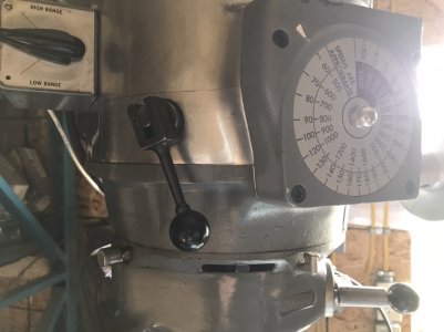
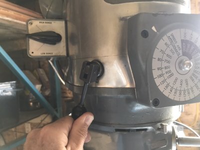
The arrow in the picture above points to the spindle brake lever. You pull it out from the head to engage and lock the brake - the handle stays put. If you rotate the lever, the brake also engages as long as you hold the lever - you can feel the pressure you apply. If you let it go, the brake disengages. IIRC, it threads into the brake band mechanism. If that gets backed out too far, the lever will not do anything.

L to R, T to B: brake off; brake on & locked; brake engaged (it normally returns to neutral when let go - I just pulled a little harder to make it stay, brake is not locked); brake engaged - lever will return to neutral - had to hold it for the picture (normal).

3D768DE8-CEB0-421A-9DCD-E37D79F90EED.jpeg 0615663C-8E5C-4260-B6F8-9911B7169364.jpeg

E06972B6-EB8E-41EC-BDDC-DC24D6F358EC.jpeg D9EE8FD0-C32C-409A-8EE9-16D197B8B354.jpeg

Cover material should be a bit more substantial than just a cloth: 1/4” plywood, OSB ( when it was still affordable is what I use with shop towels on top to soak up oil), old UHMW cutting board, rubber mat, etc., would be my choice. I have also seen aluminum sheeting. I like your idea of the liquid metal fill and contouring - will certainly stop dirt from getting in the holes. Yes, my table has some pecker marks (one is visible - there are a few more under the vise) which have zero impact on the accuracy of my machine - which is still very, very good by the way. I can totally trust my dials, I don’t have a DRO on it. For super accurate work I will install a dial indicator or a DTI.

BC1AF895-658D-4A15-9DFA-DF6E9FF609C9.jpeg 2788B670-14A8-4756-8B4D-B4EE241A58E1.jpeg

The one-shot oiler system does have a spring in it that applies pressure to the plunger pump to slowly distribute the oil. Pull up on the handle, spring pressure slowly forces it back down while the oil lubricates all the parts.

Scraping the table does normally mean that you are going to remove tiny amounts with a HSS (carbide preferred) scraper. Then check for flatness and geometry using a known standard (like a large camel back straight edge). Better would be to take the table off the machine and compare the flatness on a big surface plate. It is most likely not necessary to go to that extent (at least not initially). Stoning off all high spots should get you very close.
 
Back
Top