• Scam Alert. Members are reminded to NOT send money to buy anything. Don't buy things remote and have it shipped - go get it yourself, pay in person, and take your equipment with you. Scammers have burned people on this forum. Urgency, secrecy, excuses, selling for friend, newish members, FUD, are RED FLAGS. A video conference call is not adequate assurance. Face to face interactions are required. Please report suspicions to the forum admins. Stay Safe - anyone can get scammed.

Most Popular Low HP VFD?

lukebarber

New Member
I am trying to find a low cost alternative to KB AC drives that would work for me. The best thing that I like about the KB's is the knob for speed adjustment. It seems the others I have found are all push button. I would love to hear what everyone is using.
 
I used a Hyanyang VFD on my 3hp 3 3 phase mill. The following is a post I wrote when I installed it a couple of years ago.


The Ferro mill is 220V 3 phase and my garage is only wired for 240V single phase so I installed a Hyanyang VFD on the mill and I am happy with the results. I have is set up with a remote panel with switches for run, forward/reverse and jog as well as a variable speed potentiometer. I removed the old electrical box from the side of the mill and gutted all the old electrical stuff out of it. I mounted the box on an adjustable pedestal with the vfd and switch panel inside so it can be reached easily. After I got all the settings right I wrote a up a document and drew a schematic in case anyone else wants this information. The switch panel in the picture is temporary. I plan to make something prettier later, I just wanted to get it up and running fast.
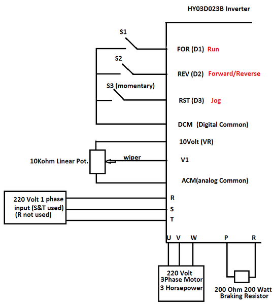


Huanyang Inverter (VFD)


-Model number HY03D023B

-Input 240 Volt single phase

-Rated output 220 Volt 3 phase 4 HP or 3KW 13 Amps (220 volts X 13 Amps = 2860 watts) (1 HP = 746 Watts) (4 X 746 Watts = 2984 Watts)


Initial Set-Up


-Instructions from vendor (eBay seller “Solar Jean”) suggested the frequency parameters be set in the following order: PD05 set to 60HZ, PD04 set to 60HZ, PD03 set to 60HZ, PD72 to 60HZ. I connected the 200 Volt single phase input power to terminals S and T and the 3 legs of the 3 phase 3 HP motor to terminals U, V, and W. I plugged the VFD in with it temporarily just lying of the table of the mill and it powered up. I set the above parameters as suggested and the Run, Forward and Reverse functions worked from the unit’s built in keypad.


Advanced Set-Up


-I wanted to use a remote mounted control panel to allow remote function of Run, Forward/Reverse, Jog as well as a Potentiometer controlled variable speed. Since the mill has a variable speed head I see no reason to run the motor at more than the rated 60HZ. Using the supplied manual I then made the following switching, wiring and parameter changes to achieve the functions I wanted. I used the schematic on page 37 as a guide for the 3 wire Run, Forward/Reverse switches and the schematic on page 12 for the wiring of the Potentiometer. Page 36 explains how the output terminals can be re-configured for multiple uses. I drew the following schematic after researching the manual. The information on pages 19-26 of the manual details which parameters and settings support the different functions. Since my custom settings are all basic they are all covered on pages 19-20 except PD72 which was part of the initial setup for 60HZ power. These are the connections and parameter changes I made to make the VFD function as I wanted:


See the schematic Switch 1 is for D1, Switch 2 is for D2 and Switch 3 is for D3.

-PD01 set to 1 to support use of external input controls.

-PD44 set to 1 to change the function of the “FOR” terminal to D1. When set to 1, D1 is now the Run function.

-PD45 set to 5 to change the function of the “REV” terminal to D2. When set to 5, D2 is now the Forward/Reverse selector. When Switch 2 is open you get forward rotation and when closed you get reverse. See page 37 of the manual for these instructions.

-PD46 set to 6 to change the function of the “RST” terminal to D3. When set to 6, D3 is now the Jog function. It works in forward or reverse depending on the position of switch 2.

-PD02 set to 1 to support the input from the external Potentiometer for speed control.

-PD11 set to 10. This sets the lowest frequency of the variable speed to 10HZ so the potentiometer can adjust the speed of the motor from 10HZ to 60HZ. The factory setting is 0 so when the pot is turned all the way down the motor stops.

-PD14 set to 5 to change the acceleration time (0Hz to 60HZ) to 5 seconds when run is selected. Factory setting is 20 seconds.

-PD15 set to 5 to change ramp down or deceleration time (60HZ to 0HZ) to 5 seconds. I was cautioned to go no lower than 5 seconds without connecting an external braking resistor. The VFD must be given time to dissipate the energy created by the motor as it slows (it acts as a generator when slowing). The internal braking circuits in the VFD cannot support aggressive deceleration and an external braking resistor must be added to slow to a stop quickly. Using the information in the manual, and some internet searches I settled on a 200 ohm, 200 watt resistor. I have ordered but not received it yet so the one show in the schematic is not wired in currently. I will update this information when I get the resistor and experiment with aggressive slow down times.


Finished product. Still working well after almost 2 years.


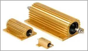
This is the braking resistor I installed.


John
 
Last edited:
I don't know much about VFD's but my lathe has a Delta VFD-M in it. the M series of VFDs from Delta is small and affordable for the hobbyist. Sizes only go up to 3 hp though.
 
Hi @John Conroy - could I trouble you to reestablish the link those pictures in your post? I'd like to see what you did here again. Thanks!
 
I edited the post and put the pictures back. I'm still pissed off at Photbucket.

Hi John
The led displays a number - is that hz? How do you know the spindle speed from that? Is it just a linear relationship eg led hz/60hz * max speed of belt setup? Nice setup. How do you like the brake?
 
My mill has a variable speed head. The display is in Hz so I can pick a speed mechanically on the mill head and then vary the frequency to tune it further. Bottom line is I only know spindle speed at 60 Hz.
 
Where is a good (cheap) place to by the braking resistor from? So far I've just used the VFD internals for braking but would assume on heavy usage/quick stops that I'd be shortening the lifespan of the VFD.

John: on my mill/VFD combo, you can program a multiplier within the VFD to extrapolate/display what would look like RPM e.g 60hz @ 1750rpm = 29.17 multiplier. There is no feedback mechanism so indeed, it was an educated guess. I did find that it was close (5%) but I wanted it closer so I then used a laser tachometer/reference point on spindle, took reading of actual rpm @ 60hz and modified multiplier slightly...now I'm within 1-2% and the values changes accordingly as you dial the speed up/down (no load situation) of the mill as long as you dont change the ratio at the machine head.

If someone wanted to really geek out they could also add closed-loop system and display real-time RPM but that was beyond my needs.
 
Luke, what do you mean by 'low HP'?

--I went with a TECO 510 unit for my 2HP mill. It has worked flawlessly, and even survived a 'spittensparken' moment. Almost any manufacturer will do and at that range they all have similar specs/features...
 
Jimbo, One of the youtube guys is using a replacement stove element to make a 2000w braking resistor. You need to take a DVM with you to measure the resistance of the coil to make sure it is compatible with your VFD. My VFD specifies a 10 ohm resistive load at 1000W, but 2000W capability won't hurt.
 
My original HM post was about threading tools & setup, but it evolved into controlling the stop of a VFD driven lathe during threading mode. I know nothing about VFD's another than I think I really want one. It doesn't look like a trivial undertaking though. When you guys are talking about braking resistor, do you mean electronics related to stopping/braking the motor itself? Is that the same functional thing as what they are calling proximity stop?

check out these threads:
https://www.hobby-machinist.com/threads/pm1340gt-lathe-threading-with-a-proximity-stop.45977/
https://www.hobby-machinist.com/threads/vfd-proximity-sensor-stop.32816/
https://www.hobby-machinist.com/thr...trol-system-with-proximity-stop-update.63426/
 
hmmmm, that gave me an idea....1500w hot water heater element could be small enough (under 8in long) and enough wattage...but I have no idea what kind of resistance are across these.

Engine block heater may be even better....anyone got an old/functional one kicking around?
 
I built a lipo battery warmer 'toaster oven' box out of banks of power resistors. That was low watts by comparison 12vDC & maybe 15A. Left unattended it could get >100C. Ask me how I know :)
At that anticipated power level how are you going to dissipate the heat of something intending to warm a tank of oil or water? Or is it just a short term load thing?
 
Hi Peter

The braking resistor we're talking about is purely for spinning down the motor faster than inertia allows; could be used in conjunction with a proximity set-up but initially you need to get the machine in a controlled spin-down situation otherwise motor braking is relatively uncontrollable/unpredicatable.

I use Lenze VFD's and although they allow motor braking internally, the DC bus the power is dumped through is quite small and therefore heats up the VFD - by adding an external braking resistor, you disperse that power through a larger resistor and redirect the heat outside of the VFD.

My original HM post was about threading tools & setup, but it evolved into controlling the stop of a VFD driven lathe during threading mode. I know nothing about VFD's another than I think I really want one. It doesn't look like a trivial undertaking though. When you guys are talking about braking resistor, do you mean electronics related to stopping/braking the motor itself? Is that the same functional thing as what they are calling proximity stop?

check out these threads:
https://www.hobby-machinist.com/threads/pm1340gt-lathe-threading-with-a-proximity-stop.45977/
https://www.hobby-machinist.com/threads/vfd-proximity-sensor-stop.32816/
https://www.hobby-machinist.com/thr...trol-system-with-proximity-stop-update.63426/
 
Ah, I see.
My heater box used banks of these in series.
 

Attachments

  • 1-5-2018 0000.webp
    1-5-2018 0000.webp
    7.6 KB · Views: 5
Back
Top