• Scam Alert. Members are reminded to NOT send money to buy anything. Don't buy things remote and have it shipped - go get it yourself, pay in person, and take your equipment with you. Scammers have burned people on this forum. Urgency, secrecy, excuses, selling for friend, newish members, FUD, are RED FLAGS. A video conference call is not adequate assurance. Face to face interactions are required. Please report suspicions to the forum admins. Stay Safe - anyone can get scammed.

Millling machine vise

ShawnR

Ultra Member
Premium Member
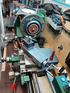
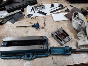
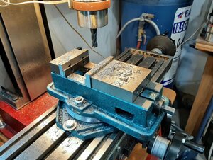
Recent projects have gotten me to use the milling vise a little more. I noticed that the moving jaw lifted when I tightened it up. Tapping down the material did not matter. Inserting a soft piece of rod on it did not matter. I could not get the back parallel to be tight. Very frustrating. And the numbers on the dial are hard to read. So, apart it came!! I have not taken one apart before so what is new for me might be familiar to you.

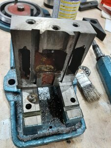
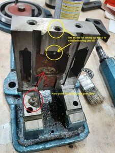
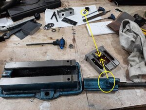
After taking it apart, I found the screw adjustment to take up the slack, and the hard point it fixes on. Now things made sense. I figured there must be something but wanted to see how it worked before just turning screws. But it was interesting to see how it was all put together. Also, how rough the casting is! When I googled the problem, I seemed to find a lot of great videos and documentation on rebuilding KURT vices but nothing on these little China imports. No one cares? :rolleyes:

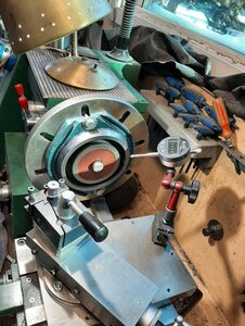
I took some measurements on the bearing, in case I can find a replacement. Not that it seems bad, but it just looks like crap. Not sure if it is worth it to replace it or not. I almost think a brass bushing would be better but I probably will not use it enough to wear it out. Having said that, I think it is better after cleaning and greasing so the bearing will probably remain.

Bottom line, after cleaning it up, filing the rough edges, lubing and adjustments, the difference is night and day! Tightening up the vise on a workpiece often leaves pressure on both parallels, or if the rear is a little loose, a light tap snugs it up. It ain't no KURT but I feel better about using it and have much more satisfaction (ie less frustration) with my setups. So if you find your import vise frustrating, check it out! Time well spent...

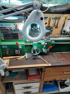
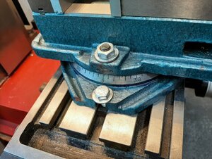
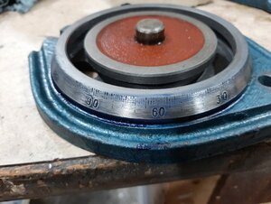
But now I need to find out a way to improve those markings. I cleaned the dial, then blued it, thinking that stuff seems pretty resistant to being rubbed off. I also wanted to see if the indentations were enough to hold a colour but nope! So I need to find a way to deepen the grooves for each one and then paint. A small dremel? Is there a tool for this? Mount the base at an angle and do in the mill? The dial sits at an angle of about 30 degrees from vertical. Any suggestions? I think that doing it free hand will look poor so I think a setup of some sort, with the right tool, is necessary.

Cheers,
Shawno
 

Attachments

  • Vise parts.jpg
    Vise parts.jpg
    189.6 KB · Views: 27
  • Poor casting.jpg
    Poor casting.jpg
    168.8 KB · Views: 29
  • Hard point.jpg
    Hard point.jpg
    178.6 KB · Views: 34
  • Dial numbers.jpg
    Dial numbers.jpg
    118.3 KB · Views: 36
  • Much better.jpg
    Much better.jpg
    175.7 KB · Views: 34
  • Hard point location.jpg
    Hard point location.jpg
    193.1 KB · Views: 25
Last edited:

ShawnR

Ultra Member
Premium Member
lol....Yes, I am! This is not normal!

And I am not even mentioning much of what I am getting done! 2 weeks into retirement and I am like a kid. Having fun!

Cheers,
 

RobinHood

Ultra Member
Premium Member
A rotary table on the milling machine should work.

Or, if you can swing it in the lathe, and have a way to index the spindle and lock it, the compound could be set at the 30*. Grind an engraving tool. Recut the graduations to an uniform depth using the compound.

Or one could use a pantograph and a rotary table.

Looks like the numbers are stamped deep enough and don’t require a redo.
 

Chip Maker

Super User
The graduations on swivel vises are more of a suggestion. If you want an accurate angle, you will need to use a sine bar and gauge blocks against the solid jaw and a dial indicator.
 

PeterT

Ultra Member
Premium Member
I wish I had the electrical smarts to come up with a drop in rotary DRO. Something you could easily adapt to a rotary table, lathe chuck, even simple swiveling mill vise like this. Push a button, zero null, displace to X number of degrees, lock in position. Guys like Clough42 are doing way more complicated things with ELS (electronic leadscrew) - sampling rotary position, intermediate computing & then displacing another stepper motor some finite turns. I just want a digital display of degrees like a DRO shows linear displacement. You would thing this would be a 'thing' but maybe I'm a misguided shop geek.
 

ShawnR

Ultra Member
Premium Member
I wish I had the electrical smarts to come up with a drop in rotary DRO. .
Someone on the internet has done it and posted it probably ....you don't need electronics experience these days. And besides, I am new here but I think there is a fair amount of the "smarts" on this board that could help.

I just want a digital display of degrees like a DRO shows linear displacement. .

Mmmm...that sounds like a great project ...:eek: If you used an encoder plate and an arduino, it actually would not be that hard to do....me thinks....

A stepper could step it fractional degrees or even doing it manually and using the arduino to do the counting/positioning feedback for you. I will put it on the list...although there are many things on that list!

But, I think you are on to something!!

The graduations on swivel vises are more of a suggestion. If you want an accurate angle, you will need to use a sine bar and gauge blocks against the solid jaw and a dial indicator.

Yea, I kinda figured that, but seeing as I took it all apart and all, I thought it would look nice.....;)


Robinhood....I will look at those options too. I remember seeing how to make key ways using the tool feed on a lathe so I guess with the right tool, this engraving could be done that way too. I will look at possibilities tomorrow.

Cheers,
 

6.5 Fan

Ultra Member
Premium Member
I removed the swivel base from my mill vise, rare; needed it and gained much needed clearance.
 

historicalarms

Ultra Member
As Chipmaker says, those graduations on those Chinese vises are, at best just a guideline. On some of these vices, the center pivot point will have enough slack in it to allow 3 or 4 graduations movement alone so you may have to attack that problem first to attain a usable accurate turntable. On my own vise (appears to be exact same product), and the pivot point was actually not bad, I had no end to frustration trameling the vise jaws to a 90 degree orientation. The way i solved that issue for myself was to trammel the vise base and swivel top exact to the mill table and then drill locating pins through the vise and base at 90 & 45 deg. Take 30 seconds to go from any angle cut to a 90 deg. cut now.
If I were doing that graduation improvement , I would use a simple small chisel and hammer and one of those lighted desk magnifying glass outfits. Even tho you would have to work slow & steady, I think the job could be very satisfactorily done in the time it would take for "set-up" of a machine cut operation. Your own patience will dictate the accuracy & presentation of the refinished product you end up with.
Unless you have a dedicated jig set up for accurate graduation spacing, even machine cutting will have much/many time consuming considerations to handle.
After engraving every line with the chisel i would give light touch with diamond file to settle any burrs on rotating surface and visual surface then emory cloth to smooth out and then paint, then emory cloth again...should leave a very visible representation .
 

ShawnR

Ultra Member
Premium Member
Tackled the engraving today. Interesting. Set up took a while to figure out and do but after that, kind of a rewarding exercise.
Made a few screw ups (as per my protocol, apparently :rolleyes: ) so certainly not perfect but way better than it was.

Basically, what Robin suggested...Thanks @RobinHood

Thanks for the all of the advice.

Cheers,
Shawno
 

Attachments

  • Base set up1.jpg
    Base set up1.jpg
    205.2 KB · Views: 13
  • Dialing it in.jpg
    Dialing it in.jpg
    185.4 KB · Views: 13
  • Base set up3.jpg
    Base set up3.jpg
    186.5 KB · Views: 14
  • New lines2.jpg
    New lines2.jpg
    182.6 KB · Views: 14
  • Old Dial lines.jpg
    Old Dial lines.jpg
    118.3 KB · Views: 11
Last edited:

ShawnR

Ultra Member
Premium Member
A few things I learned along the way...

Tool bit needs to be centered just like when using the lathe...huh...who woulda thunk? :rolleyes: First couple were angled...
I experimented with different cutter profiles but found that a smaller bit (1/4" I think) and sharpened so that the top edge was doing the cutting allowed the easiest to view and align
I set up the compound for the bevel of the dial, and set it to bottom out at the end of each group of lines I was doing, ie the 10's (longest ones), then the 5's, then the singles.
I locked the carriage and had the lathe in a low gear so that it held well enough but I could still rotate it.
And of course, good lighting and a magnifier, and cheaters.....:)

Lots of setting up but the actual engraving went well.
 
Top