• Scam Alert. Members are reminded to NOT send money to buy anything. Don't buy things remote and have it shipped - go get it yourself, pay in person, and take your equipment with you. Scammers have burned people on this forum. Urgency, secrecy, excuses, selling for friend, newish members, FUD, are RED FLAGS. A video conference call is not adequate assurance. Face to face interactions are required. Please report suspicions to the forum admins. Stay Safe - anyone can get scammed.

Mill Speed Controller

whydontu

I Tried, It Broke
Premium Member
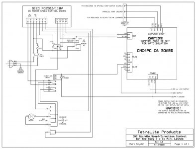
My BB CT129 milling machine uses a 90 volt DC motor with a KBIC-120 variable speed control. Speed is set using a simple rotary pot. There is an auxiliary input that stops the motor without disconnecting power to the speed control.

My last project was to build a non-contact tachometer with a simple microcontroller that lets me dial-in the cutter size and then the microcontroller calculates the SFM speed based on the cutter RPM.

Doing a deeper dive into the KBIC-120 owners manual, I discovered the motor speed can be adjusted by an external 0 to 7 volt dc signal.

The new project will modify the tachometer to combine it with the speed control function.

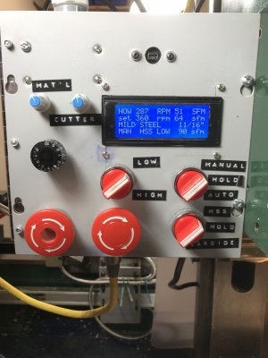
Dial #1 to select workpiece material
Dial #2 to select cutter size
Dial #3 to set cutter RPM for manual operation
Off / Manual / Automatic switch with indicator lights
Big red STOP button that stops the spindle but leaves all the settings intact
Even bigger red STOP button that shuts off everything
LCD display, 20 characters wide x 4 rows high
All in an 8”x8” metal enclosure

in use, the controller will display material, cutter size, recommended SFM based on Machinists Handbook charts, recommended RPM based on these three bits of information, and actual cutter RPM. In Manual mode, dial #3 will adjust motor speed. In Automatic mode the controller will adjust cutter speed by software, ignore dial #3, and output a proportional 0-7 volt signal to the motor speed controller. Automatic mode will be closed-loop feedback to maintain proper RPM by comparing calculated RPM setting to actual spindle RPM.

The display will look like this:

Mat’l: ALUMINUM
Cutter Dia.: 11/16”
RPM: 300 SFM: 50
Spindle RPM: 280

I‘m about 20% along the way. I’ve breadboarded the microcontroller, written software for the display and tachometer functions. Next tricky step is to write the automatic functionality. Then bench test, fix bugs, make the enclosure for all the sub-assemblies, and engrave a new front panel. Maybe $200 total in parts, including the enclosure.

When and if I get this all working I’ll post more info.

FYI - most VFDs will accept a 4-20mA proportional control signal to adjust motor RPM. With one component change the microcontroller can easily be modified to produce this type of signal.
 
Since your machine uses a DC motor no VFD is needed. VFD is only used for 3ph AC motors. Unless you drop serious $$ there are a few draw backs with VFD systems.

That said I have installed VFD on my mill this year.
 

Susquatch

Ultra Member
Administrator
Moderator
Premium Member
Since your machine uses a DC motor no VFD is needed. VFD is only used for 3ph AC motors. Unless you drop serious $$ there are a few draw backs with VFD systems.

That said I have installed VFD on my mill this year.

I don't think @whydontu was planning a VFD on his system. I think that comment of his was intended to point out that his system could easily be modified to work for others who have 3ph motors and VFDs........ LIKE ME! Wooo Hooo!
 

whydontu

I Tried, It Broke
Premium Member
no power feeds. I’ve tried the generic mini-mill power feeds, and the purpose-built one from Grizzly for the G0704, and they were more pain than they were worth.

As a previously long-haired hippy-ish baby boomer, I usually explain it like a Zen thing. Rotating the mill hand wheels, listening for that perfect feed rate that sings, with nice curling chips, is very satisfying. I have a cnc engraver, and watching it is like watching paint dry.

I use the power feed on my lathe, only because it’s so hard to get a smooth even turn using the very coarse and/or awkward longitudinal feed on my BB B2227. But it’s really enjoyable to do a manual feed when I get it just perfect and the chips are curling off sounding like frying bacon.
 

Susquatch

Ultra Member
Administrator
Moderator
Premium Member
As a previously long-haired hippy-ish baby boomer, I usually explain it like a Zen thing. Rotating the mill hand wheels, listening for that perfect feed rate that sings, with nice curling chips, is very satisfying. I have a cnc engraver, and watching it is like watching paint dry.

I needed to hear that.... It explains a lot of my own lust for manual operation.

There is also a certain tactile feedback that comes with manual feed.

I like analog displays for some of the same reasons but mostly because a well built analog display doesn't lie. I do like your digital ones though. But then again, you programmed them yourself so you know how they work and what they do (and do not) display.

Some day some idiot will come up with an automatic DNA transfer device for human reproduction with a digital display of transfer speed, volume, rate, and efficacy. I'm glad I lived in the dark ages.
 

whydontu

I Tried, It Broke
Premium Member
@whydontu how about a control that increases a speed as you get closer to the centre on a facing cut? :eek:
Actually not that tricky to do.

Needs a limit switch at the inner end position.
Needs a limit switch or start switch to sense when the cut is started
Needs the material info
Needs to know the cutter feed rate in inch per workpiece revolution
Needs to know the O.D. and I.D. of the cut.

On paper it looks way more complicated than it would be to make. A keypad, a microcontroller, an LCD display, some programming.

The amazing thing about old-school USA engineering is a lot of these functions are done using hydraulics in Monarch lathes, read the patent abstract for United States Patent 2381422. Unfortunately, since I retired in August I don’t have access to the glorious Monarch 62 lathe at my final employer.


whydontu

I Tried, It Broke
Premium Member
I needed to hear that.... It explains a lot of my own lust for manual operation.

There is also a certain tactile feedback that comes with manual feed.

I like analog displays for some of the same reasons but mostly because a well built analog display doesn't lie. I do like your digital ones though. But then again, you programmed them yourself so you know how they work and what they do (and do not) display.

Some day some idiot will come up with an automatic DNA transfer device for human reproduction with a digital display of transfer speed, volume, rate, and efficacy. I'm glad I lived in the dark ages.
I’ve even gone so far as to ditch the cordless drills and other than the bench mill @ drill press my workbench has two other devices for making and cleaning up holes - a nice corded Milwaukee 1/2” drill, and a old-school Stanley brace & bit modified with a keyless three-jaw chuck. The brace is faster than the Milwaukee for most drilling operations in light-gauge stuff, and does a way better job countersinking or cleaning up holes. Also works great with step drills, never goes too deep.
 

Attachments

  • A73D211C-42AA-4471-B474-35AF3978718B.jpeg
    A73D211C-42AA-4471-B474-35AF3978718B.jpeg
    36.5 KB · Views: 2

Susquatch

Ultra Member
Administrator
Moderator
Premium Member
a old-school Stanley brace & bit modified with a keyless three-jaw chuck.

I had one of those for many many years. Sadly, somebody thought they needed it more than me..... I never saw it again.
 

whydontu

I Tried, It Broke
Premium Member
that was today’s brain stretch. added a switch to select HSS or carbide tooling. decided that full automatic with closed-loop feedback is too dangerous, but will implement a flashing alarm light if the cutter speed is +/- 10% from the calculated speed.
 

whydontu

I Tried, It Broke
Premium Member
more brain stretching. I must have looked at twenty different material vs, sfm charts, and no two match. there’s probably 2:1 ratio between lowest and highest. I do lots of aluminum work. Little Machine Shop is 500-600 sfm for 6061T6, WISC is 150-300, Grizzly shows 300. if I use my machining app, it uses 300 but shows a required horsepower way higher than my 3/4 HP mill can do. i’ll enter sfm as an array so it’s easy to change values.
 

Mcgyver

Ultra Member
decided that full automatic with closed-loop feedback is too dangerous, but will implement a flashing alarm light if the cutter speed is +/- 10% from the calculated speed.

Automatic is nice, but manual with a dial captures 95% of the advantage.....it would great to have for facing large pieces
 

whydontu

I Tried, It Broke
Premium Member
and more research. the design of my BB CT129 or the equivalent Grizzly G0704 mill uses a motor control board very similar to the ones used on the Chinese 7xXX mini lathes. all of these can have speed control done by an external 0-7 or 0-10 VDC signal. which means my design should also work other machines with only a bit of software changes. starting testing later this week, as long as SWMBO doesn't object to me spending the next week hunkered down in the shop
 

Attachments

  • C5555777-8D1B-45F2-B1EA-551AA780FDFA.jpeg
    C5555777-8D1B-45F2-B1EA-551AA780FDFA.jpeg
    74.5 KB · Views: 6

whydontu

I Tried, It Broke
Premium Member
Almost there. Controller electronics & mechanical has been completed and installed on mill. Still need to complete software, stuff to be done:
> update Arduino code to operate under automatic control
> update code to react properly to changing from low to high speed using the mechanical gears
> set scale factors in the code so the control dial setting matches the actual spindle RPM
> pretty up the front panel and get rid of the Demo labels.
> make up nicer knobs

LCD display:

Top line - actual RPM, actual SFM based on selected cutter size and actual RPM
Second line - dialled in RPM, calculated SFM based on speed dial, cutter material, and cutter diameter
Third line - workpiece material, cutter diameter
Fourth line - shows settings of switches

Top left-hand grey knob selects workpiece material
Top right-hand grey knob selects cutter diameter

Black knob adjusts motor RPM under <manual> control

Two big red button - left hand is master power, middle button is Hold override. Hold override stops everything but leaves the LCD display at the last configuration.

Middle switch changes scales to match actual mill gear setting
Top left-hand switch selects <Manual><Hold><Auto> spindle RPM control. <Manual> reads the black dial and adjusts mill RPM, <Auto> sets mill RPM from the workpiece, cutter diameter, and cutter material
Bottom left-hand switch selects <HSS><Hold><Carbide> cutter material, and is used to calculate best SFM from a look-up table and cutter diameter

Putting either of the right-hand switches to Hold also stops the spindle, and changes the LCD display to match desired settings.

the KBIC-120 control board has been adjusted to nice slow ramp to full speed, I might tweak it a bit to speed up the ramp.

Lynyrd Skynyrd playing in the background, just because it should be playing will working in the shop.

Videos:


Attachments

  • Controller Panel 1.jpg
    Controller Panel 1.jpg
    300.7 KB · Views: 8
Top