• Spring 2024 meetup in Calgary - date Saturday, April 20/2024. discussion Please RSVP Here to confirm and get your invitation and the location details. RSVP NOW so organizers can plan to get sufficient food etc. It's Tomorrow Saturday! you can still RSVP until I stop checking my phone tomorrow More info and agenda
  • We are having email/registration problems again. Diagnosis is underway. New users sorry if you are having trouble getting registered. We are exploring different options to get registered. Contact the forum via another member or on facebook if you're stuck. Update -> we think it is fixed. Let us know if not.
  • Spring meet up in Ontario, April 6/2024. NEW LOCATION See Post #31 Discussion AND THE NEW LOCATION

Mill Riser Idea

Janger

(John)
Administrator
Vendor
Hi,

My mill has a fairly short ability to lower the table. It goes way up high in the air but for dropping the table it does not go down all that low. This is partly because there is a lot of extra metal to allow the table to swivel. This is a problem when drilling. By the time I add a drill chuck and a drill there is very little clearance above the vise. Depending on the bit it might be 1/2".

So I had this idea to lift the ram head up higher by making a riser block and installing it where the ram swivels. See pictures.

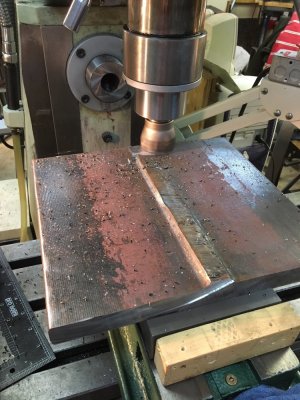
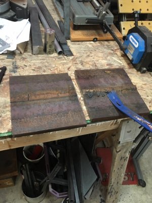
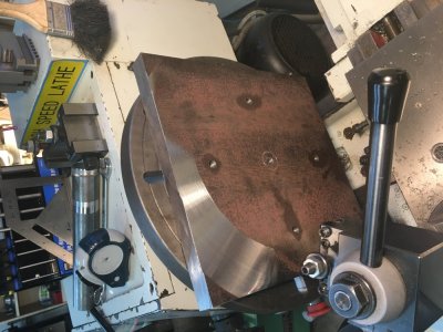
First is riser block design. 1" plates with welded on 35mm diameter solid stock columns.

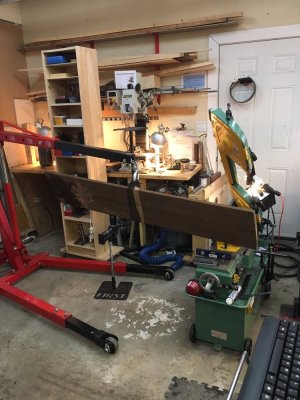
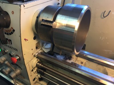
Second picture - The mill with the ram head removed - so the riser block would go on top of this.

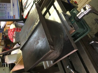
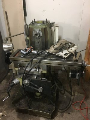
Third picture - The mill from the side showing the ram head.

Anybody ever done this sort of thing? Would this work? I could buy shorter drill bits - spendy. The table can't go any lower either as the dovetail ends. I could give up on vertical drilling and just use the horizontal but that's not especially convenient. The Z table adjustment is not automated either.

Anybody got some 1" plate to make two 10" by 10" plates I could buy trade etc?

Thanks everyone
 

Attachments

  • Mill Riser.jpeg
    Mill Riser.jpeg
    63.2 KB · Views: 37
  • IMG_1368.JPG
    IMG_1368.JPG
    115.1 KB · Views: 40
  • IMG_1731 2.JPG
    IMG_1731 2.JPG
    140.5 KB · Views: 39
Last edited:

Janger

(John)
Administrator
Vendor
Plate prep....

The plate is the side of an I beam hence the flange part in the middle. It's 1" by about 11" by 5'. Perhaps 175lbs.

Instead of making columns John C found me a piece of 10" diameter thick wall pipe. I'll be using that instead. Pictures are in reverse order.
 

Attachments

  • IMG_1749.JPG
    IMG_1749.JPG
    168.8 KB · Views: 30
  • IMG_1748-1.JPG
    IMG_1748-1.JPG
    148.8 KB · Views: 27
  • IMG_1746.JPG
    IMG_1746.JPG
    143.8 KB · Views: 27
  • IMG_1744.JPG
    IMG_1744.JPG
    145.1 KB · Views: 26
  • 53704155389__B4C71064-1912-4210-9586-05DEC6E54B28-1.JPG
    53704155389__B4C71064-1912-4210-9586-05DEC6E54B28-1.JPG
    188.4 KB · Views: 27

Alexander

Ultra Member
Administrator
How did milling the plate flat go? Also did you motorized the quill or why is it down while milling? It would be a bit more rigid up. That is a big chunk to mill off and every little bit of rigidity will help
 

John Conroy

member
Premium Member
Lots of work but it should be a big improvement. The thick wall pipe will be more rigid than the 4 seperate risers I think.

John
 

Janger

(John)
Administrator
Vendor
More photos. Fun project learning lots.
John suggested using the lathe to surface the plate as flat as possible. That is working pretty well. The corners of the stock on the faceplate clear the ways by about 1/4”. First three photos show how it should come together. Next 3 show facing on the lathe.
 

Attachments

  • 12C78AD8-5E01-4BAA-9BFB-4428DDBCBB92.jpeg
    12C78AD8-5E01-4BAA-9BFB-4428DDBCBB92.jpeg
    127.4 KB · Views: 17
  • 59EC5A67-7297-49D0-A7F5-AAB7A0E192F4.jpeg
    59EC5A67-7297-49D0-A7F5-AAB7A0E192F4.jpeg
    142.8 KB · Views: 18
  • C94E06EF-2CFE-4394-87AE-D082FCC53B58.jpeg
    C94E06EF-2CFE-4394-87AE-D082FCC53B58.jpeg
    145.1 KB · Views: 16
  • C66FAED7-0010-43A6-A119-A3F6B17268A5.jpeg
    C66FAED7-0010-43A6-A119-A3F6B17268A5.jpeg
    125.7 KB · Views: 17
  • 249CC566-E63E-44B5-9409-0EBF1EE0BEF7.jpeg
    249CC566-E63E-44B5-9409-0EBF1EE0BEF7.jpeg
    149.4 KB · Views: 19
  • 1AE86CBF-EE27-4B20-AD35-7239DDEA9E6D.jpeg
    1AE86CBF-EE27-4B20-AD35-7239DDEA9E6D.jpeg
    126 KB · Views: 19
Last edited:

Janger

(John)
Administrator
Vendor
strange gold swarf. Killer tough material. Had to sharpen carbide c6 brazed tool over and over.
 

Attachments

  • B4DE5A5C-2510-4195-B67F-50EED39B9F45.jpeg
    B4DE5A5C-2510-4195-B67F-50EED39B9F45.jpeg
    157.7 KB · Views: 13
  • 10BB4E97-E083-44D1-A0C2-A3145C3C7123.jpeg
    10BB4E97-E083-44D1-A0C2-A3145C3C7123.jpeg
    91.9 KB · Views: 12
  • 062D00AC-5E76-467C-A0B8-9F43F879412D.jpeg
    062D00AC-5E76-467C-A0B8-9F43F879412D.jpeg
    162 KB · Views: 13

Janger

(John)
Administrator
Vendor
Slow mo turning oil pipe for appearance. The video is a little too long.


Sharpening with inexpensive diamond wheel in the rotary tool. Wheel is from Princess Auto and was not expensive. I find this works better than the diamond hand file. The dryer tube is my exhaust fan.
 

Attachments

  • C3E3533E-2EAC-4705-A1F4-4134BF681F27.jpeg
    C3E3533E-2EAC-4705-A1F4-4134BF681F27.jpeg
    130.2 KB · Views: 16
  • F7E45B07-1D63-433E-A0BB-BE7221131B52.jpeg
    F7E45B07-1D63-433E-A0BB-BE7221131B52.jpeg
    123.2 KB · Views: 14

Janger

(John)
Administrator
Vendor
Annealing riser pipe. After reading various sources it appears welding this riser in it's hardened state may lead to cracking. Annealing is recommended so I tried that. I've been told the anneal went well and it's now dead soft. Also recommended is a preheat and postheat before and after the welding. I've ordered the right metric hex bolts to match the mill and am finishing the plates.
 

Attachments

  • 7DFC15B6-5CEF-4A8D-B2A5-20A59F5856A3.jpeg
    7DFC15B6-5CEF-4A8D-B2A5-20A59F5856A3.jpeg
    129.2 KB · Views: 9
  • 32B5FAAB-611C-4340-B4AA-B6B245ECCD53.jpeg
    32B5FAAB-611C-4340-B4AA-B6B245ECCD53.jpeg
    130.9 KB · Views: 9

Janger

(John)
Administrator
Vendor
Man it’s been more than a year since I worked on this.... gotta get this done.
 

Janger

(John)
Administrator
Vendor
So while I’m waiting for this slow and loud mill cycle on the golf club to finish I’ll post about the mill riser. I made a mistake a year ago and this put me off. The centre holes I’m pointing at are off by about 0.25” . This was because I had to slide the head further out as the distance is too far to reach. I messed up on the coordinates after. So even with Cnc the coordinates are precise but screw ups are still what? Plentiful? :mad:

So I need to dial it in better and hurry less.
 

Attachments

  • 19D5C4B5-3FF5-42BF-A1EF-D077CAF37316.jpeg
    19D5C4B5-3FF5-42BF-A1EF-D077CAF37316.jpeg
    96 KB · Views: 0

Tom Kitta

Ultra Member
yeah that did happen to some of my project - managed to sell the tool before making all upgrades to it!
 
Top