Ironman
Ultra Member
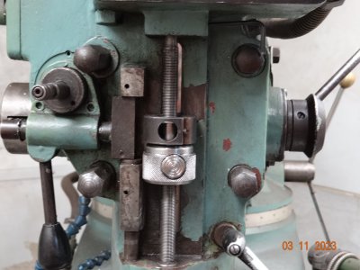
Repeated hole drilling to a set depth means twiddling with the stop collars on the mill for 5 minutes til you get it where you want it, and then doing it all over again when you want full stroke. So I made myself a push button quick lock setup. The thread on the depth stop is 12x1mm, of course I had to order a tap
I started sifting through all the stub ends from projects completed in the past. Needed a short bit of 1.75 CR and a piece of 3/4" stock.
It's hard to believe, but I don't have one. So a stub of 1" had to be turned down.
I found a little bit of 1.75", barely enough to grab in the chuck as there was a bit of whittling to do. I managed to machine away the damages on it, almost...and then knurled it. Flipped it around in the jaws and grabbed the knurled end with some pop can shims to protect the knurl, and bored it to 12mm. Then I could stabilize with the live center, and machine the collar that goes up into the quill block.
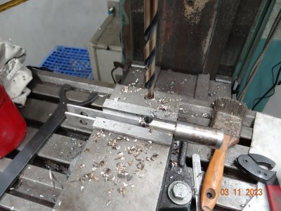
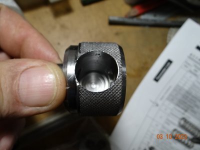
Now the fun part. I have to bore a hole into it for the half nut button thing, and make some relief for a spring, all without punching through the other side.
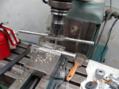
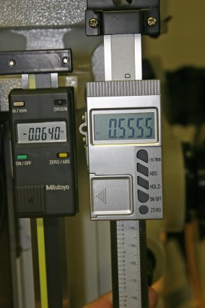
I'm sure there is a proper way to do this, but lacking the know how, I drew it out on the plasma program to scale, and made .100 as my safety margin to breakthrough. I measured the depth on the screen, and then used a 3/4" end mill to drill down the required depth, and it worked. Then I threaded the stock that will be my button, and as in the 3rd picture, I moved over and used a 1/2 endmill to punch out space for the threaded rod when disengaged. It took a little filing and fiddling til I had a smooth transition from thread engaged to disengaged position.
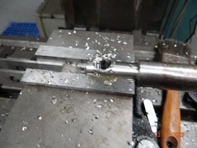
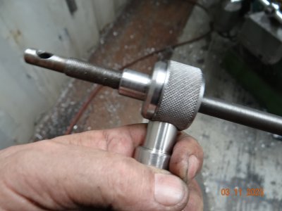
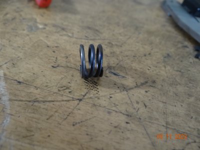
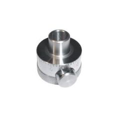
Picture 4 shows a test assembly of the gizmo. In #5, I had to find a spring the right size and cut it and pull some temper so it was not too stiff. The spring fits in the hole shown in #6, then the threaded rod slides in and the spring pushes the half nut into the rod to engage. Push the button in to disengage the halfnut and slide it to where you want it.
It works fine. My explanation may be a bit lacking....
I started sifting through all the stub ends from projects completed in the past. Needed a short bit of 1.75 CR and a piece of 3/4" stock.
It's hard to believe, but I don't have one. So a stub of 1" had to be turned down.
I found a little bit of 1.75", barely enough to grab in the chuck as there was a bit of whittling to do. I managed to machine away the damages on it, almost...and then knurled it. Flipped it around in the jaws and grabbed the knurled end with some pop can shims to protect the knurl, and bored it to 12mm. Then I could stabilize with the live center, and machine the collar that goes up into the quill block.
Now the fun part. I have to bore a hole into it for the half nut button thing, and make some relief for a spring, all without punching through the other side.
I'm sure there is a proper way to do this, but lacking the know how, I drew it out on the plasma program to scale, and made .100 as my safety margin to breakthrough. I measured the depth on the screen, and then used a 3/4" end mill to drill down the required depth, and it worked. Then I threaded the stock that will be my button, and as in the 3rd picture, I moved over and used a 1/2 endmill to punch out space for the threaded rod when disengaged. It took a little filing and fiddling til I had a smooth transition from thread engaged to disengaged position.
Picture 4 shows a test assembly of the gizmo. In #5, I had to find a spring the right size and cut it and pull some temper so it was not too stiff. The spring fits in the hole shown in #6, then the threaded rod slides in and the spring pushes the half nut into the rod to engage. Push the button in to disengage the halfnut and slide it to where you want it.
It works fine. My explanation may be a bit lacking....