• Scam Alert. Members are reminded to NOT send money to buy anything. Don't buy things remote and have it shipped - go get it yourself, pay in person, and take your equipment with you. Scammers have burned people on this forum. Urgency, secrecy, excuses, selling for friend, newish members, FUD, are RED FLAGS. A video conference call is not adequate assurance. Face to face interactions are required. Please report suspicions to the forum admins. Stay Safe - anyone can get scammed.

Metric Threading on an Imperial Lathe

Susquatch

Ultra Member
Administrator
Moderator
Premium Member
I was wondering how a metric threading dial works and ran across a really cool tip on cutting metric threads with an imperial lathe.

I've always thought you had to leave the half nut engaged while you start, cut thread, stop, retract cross slide, reverse, stop, return cross slide, advance threading tool on compound, start, and repeat. But this method significantly increases the risk of a crash when threading to a shoulder.

Turns out that it isn't necessary after all.

The trick is to cut the thread as usual, disengage the half nut as usual, then stop the lathe, then reverse the lathe and engage the half nut when the threading dial gets to whatever you had it on for the first pass.

Essentially, this is like never releasing the half nut - except you do. You just use reverse to get back to exactly where you were when you disengaged it.

I tried it myself today and it works like a charm.

Maybe some of you already knew that. But I didn't and I love it. I'll never be reluctant to cut metric threads again.
 

Susquatch

Ultra Member
Administrator
Moderator
Premium Member
How about that! Turns out that Lipton found out about it the same place that I did and decided to do a video on it. So it looks like I'm in good company. He didn't know about it either.

Anyway, I hope somebody here finds the method useful.
 

Tom Kitta

Ultra Member
I was going to finish the threat topic with "is a pain".

At least on my small lathe I need to change gears to get metric threads.

On my big lathe I have a cool "joystick" gearbox - so no issues.
 

Darren

Ultra Member
Premium Member
on my standard modern 1660, you leave the half nuts engaged during the entire threading operation, standard or metric threads. You disengage the leadscrew and reverse it on the fly, never reversing the spindle. It doesn't even have a thread chasing dial. Its pretty nice for threading, and foolproof.

The lipton method is pretty good too. Here's an awesome video on this topic:


RobinHood

Ultra Member
Premium Member
on my standard modern 1660, you leave the half nuts engaged during the entire threading operation, standard or metric threads. You disengage the leadscrew and reverse it on the fly, never reversing the spindle. It doesn't even have a thread chasing dial. Its pretty nice for threading, and foolproof.
It sounds like they are using a dog clutch like Hardinge (and their knock offs). Very cool system indeed.

@Susquatch , thanks for sharing - been using this procedure for about 7 years. Works great. For me it started with my metric SM1340. It did not have a spindle brake. Threading to a shoulder in SAE was a huge deal. So I needed to find a better way. I think I saw Joe Pie’s video at some point after I had discovered the procedure by trial & error.
 

deleted_user

Super User
I was wondering how a metric threading dial works and ran across a really cool tip on cutting metric threads with an imperial lathe.

I've always thought you had to leave the half nut engaged while you start, cut thread, stop, retract cross slide, reverse, stop, return cross slide, advance threading tool on compound, start, and repeat. But this method significantly increases the risk of a crash when threading to a shoulder.

Turns out that it isn't necessary after all.

The trick is to cut the thread as usual, disengage the half nut as usual, then stop the lathe, then reverse the lathe and engage the half nut when the threading dial gets to whatever you had it on for the first pass.

Essentially, this is like never releasing the half nut - except you do. You just use reverse to get back to exactly where you were when you disengaged it.

I tried it myself today and it works like a charm.

Maybe some of you already knew that. But I didn't and I love it. I'll never be reluctant to cut metric threads again.
so I made my end stop switches for nothing... well not really
 

YYCHM

(Craig)
Premium Member
I don't understand the problem here? If you have the gearing to make metric threads why can't you just disengage the nut back up and go again?
 

Darren

Ultra Member
Premium Member
I don't understand the problem here? If you have the gearing to make metric threads why can't you just disengage the nut back up and go again?
you can do that on an imperial lathe cutting imperial threads, no problem with a thread dial, and on a metric lathe cutting metric threads which are a multiple of the leadscrew pitch, but not on an imperial lathe cutting metric threads, or a metric lathe cutting imperial. Did you watch the videos?
 

Susquatch

Ultra Member
Administrator
Moderator
Premium Member
I don't understand the problem here? If you have the gearing to make metric threads why can't you just disengage the nut back up and go again?

Not sure what you are asking @YYCHM . On my imperial lathe, cutting metric threads with a 127 gear installed, opening the half nut and cranking back the carriage to the start point looses synchronization between the spindle (part I'm threading) and the leadscrew. So the tool bit does not end up in the thread groove even if you choose the same thread dial setting.

My manual (and every manual and every text book and every video I have ever looked at until these recent discoveries) says you have to leave the half nut engaged for every pass of the entire threading operation - reversing the lathe after each pass.

My lathe does not have a brake. So leaving the nut engaged significantly increases the risk of crashing when threading to a shoulder.

With this new discovery (new to me that is), I don't have to do that anymore. I can simply disengage the half nut just like I always used to do.

The only difference between cutting a metric and an imperial thread now is that I have to engage the half nut in reverse now instead of cranking the carriage back and then engaging it.

Edit - come to think of it, I could use this metric method for threading imperial threads too and then not worry about training myself to follow two different habits.
 
Last edited:

6.5 Fan

Ultra Member
Premium Member
I used the method Sasquatch described for metric threads and screwed it up some how anyway. Never had a problem with any other threads, and i actually like threading. Sold the machine before i could figure out where i was going wrong. May have to try metric on my old Colchester if i have the proper gears.
 

Susquatch

Ultra Member
Administrator
Moderator
Premium Member
so I made my end stop switches for nothing... well not really

Your sense of humour cracks me up sometimes......

On a serious note though, my lathe has no brake so I'd be very leary of using an end stop switch myself.

But sometime in the next year or so, I will install a 3ph motor and vfd in the lathe and that may provide adequate braking.
 

DPittman

Ultra Member
Premium Member
This method does not work with my lathe .

My lathe does not have a separate feed rod for non threading carriage travel but instead like many small lathes, it uses the lead screw for both non threading carriage travel and when threading. It does this dual duty by using a key slot that is cut the entire length of the lead screw. The have nut engages on the lead screw threads and the non threading carriage travel mechanism engages in the key slot. The thread chasing dial only works smoothly when leadscrew is turning in regular tailstock to headstock direction. When turning in opposite direction the keyway in the leadscrew comes up on the bottom of the thread chasing dial gear and catches it in a bad way. By that I mean it does not engage in the teeth of the thread dial gear but rather on the edge of the gear teeth and then there is bad forces and things happening as the lead screw is now binding on the edge of the thread chasing dial gear.

I'm not sure I can show this issue very well in pictures but if anyone is interested I can attempt to show/explain further. I suspect it will not interest anyone else if you don't have the same setup as me.

Edit
There is nothing wrong with the reversing method as described in the videos but rather the problem lies with my oddball setup. Possibly a different threading dial/gear might fix the problem for me.
 
Last edited:

RobinHood

Ultra Member
Premium Member
@DPittman , I agree, it is a problem of the thread dial set-up on your lathe. The process works for any lathe, single or multiple shaft.

How do you produce a LH thread? Does the dial bind up?
 

DPittman

Ultra Member
Premium Member
@DPittman , I agree, it is a problem of the thread dial set-up on your lathe. The process works for any lathe, single or multiple shaft.

How do you produce a LH thread? Does the dial bind up?
I think I only have cut one left hand thread before (at least on purpose) and I just would remove the thread chasing dial mechanism altogether from engagement and leave everything in gear including keeping the half nut engaged.
 

deleted_user

Super User
Edit - come to think of it, I could use this metric method for threading imperial threads too and then not worry about training myself to follow two different habits.
Hence my end switches... always the same technique. I usually only single point shorter threads so leaving half nut engaged for me is not a chore.
 

PeterT

Ultra Member
Premium Member
My lathe does not have a separate feed rod for non threading carriage travel but instead like many small lathes, it uses the lead screw for both non threading carriage travel and when threading. It does this dual duty by using a key slot that is cut the entire length of the lead screw.
You are not the first person to raise this issue. And who knows, might even be the basis for some of the original advice. My lathe is configured like the Tom Lipton vid - power feed shaft (solid rod with key that runs the length) and threading rod (fully threaded, no interruptions). You can only be in one mode or the other.

On lathes where they combine threading & feeding on a single shaft with threads & key slot... hmm I'd have to noodle upon that. One one hand I cannot see why the threading dial should care which way the rod is rotating, its just following the thread pitch & spinning the dial. Some dials pivot & orient different to the screw to either run or disengage, but I would think in the end the 2 gears must be tangent/engaged. I can envision slight backlash issues where re-engagement in opposite direction isn't quite exactly on exact same position if half nuts are worn

I would love a reliable mechanical disengagement mechanism. Some lathes have this integrated, but not many Asia machines adopted until you get to the bigger or tool room models unfortunately. I followed some VFD conversion builds with the limit switches & such. My (limited) understanding is that is another 'depends' type thing. Higher rpm & rotation mass means more braking power required so dissipate energy so separate braking resistors may be required. Others have programmed a 'rapid ramp down' curve to stay within VFD limits & still provide operator time, but keeps the speed up for 98% of threading. Its a bigger deal on coarse threads where the disengagement time interval is proportionately shorter before bad things happen.

One of the AMEN guys built the Clough42 ELS on his Emco & showed a demo vid. That is a sweet setup. Imperial, Metric, obscure watchmaker - no problemo. But you have to have some electrical skills to do the retrofitting. My brain has low RAM limitation.
 

DPittman

Ultra Member
Premium Member
You are not the first person to raise this issue. And who knows, might even be the basis for some of the original advice. My lathe is configured like the Tom Lipton vid - power feed shaft (solid rod with key that runs the length) and threading rod (fully threaded, no interruptions). You can only be in one mode or the other.

On lathes where they combine threading & feeding on a single shaft with threads & key slot... hmm I'd have to noodle upon that. One one hand I cannot see why the threading dial should care which way the rod is rotating, its just following the thread pitch & spinning the dial. Some dials pivot & orient different to the screw to either run or disengage, but I would think in the end the 2 gears must be tangent/engaged. I can envision slight backlash issues where re-engagement in opposite direction isn't quite exactly on exact same position if half nuts are worn

I would love a reliable mechanical disengagement mechanism. Some lathes have this integrated, but not many Asia machines adopted until you get to the bigger or tool room models unfortunately. I followed some VFD conversion builds with the limit switches & such. My (limited) understanding is that is another 'depends' type thing. Higher rpm & rotation mass means more braking power required so dissipate energy so separate braking resistors may be required. Others have programmed a 'rapid ramp down' curve to stay within VFD limits & still provide operator time, but keeps the speed up for 98% of threading. Its a bigger deal on coarse threads where the disengagement time interval is proportionately shorter before bad things happen.

One of the AMEN guys built the Clough42 ELS on his Emco & showed a demo vid. That is a sweet setup. Imperial, Metric, obscure watchmaker - no problemo. But you have to have some electrical skills to do the retrofitting. My brain has low RAM limitation.
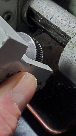
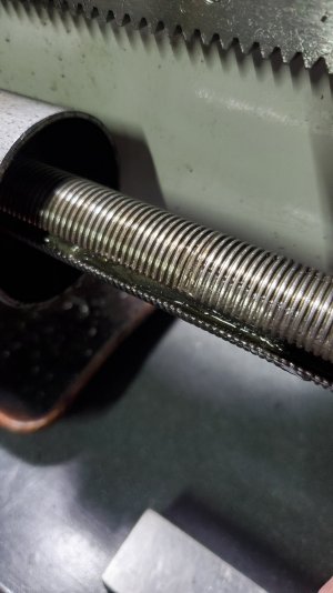
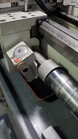
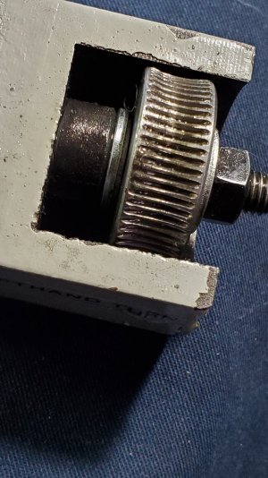
I wanted to take a few pictures to better explain my problem and in doing so I had to take things apart a little to show them better.
Typically when the lead screw was turning for lefthand threads (carriage movement towards tailstock) and I would try to engage the threading dial the notched keyway in the leadscrew got caught on the thread dial gear and tried to cause all sorts of carnage then. There are a couple of different mounting holes for the thread dial on the carriage but the second one is not even remotely correct for my set up and so I just avoided engaging the thread dial anytime the leadscrew was going towards tailstock.
One thing that sort of surprised me is how the thread dial gets disconnected from the lead screw once the half nut lever is engaged. There is obviously enough slack/movement in the lead screw to allow it to move out of synchronization with the thread dial when half nut is engaged. I assumed that this slack along with the keyway on the lead screw was what was causing my issue with lefthand threading.
Today I've come to a different conclusion. It didn't make sense to me that the thread dial worked ok in one direction but not the other. Upon closer observation I think it has to do with where the leadscrew is engaging with the thread dial gear. I believe the thread dial gear was simple too high on the leadscrew and worked ok when the keyway was coming down from the top into mesh with the gear butvwas catastrophic when the keys lot came up from the bottom and tried to mesh with the gear.
My solution (hopefully) was simply to add spacers to bring the thread dial gear down lower to mesh closer to the center of the leadscrew.
I'm a bit gun shy of trusting this modification as the fix as if I am wrong the thread dial jamming against the leadscrew could be very serious. I'm lucky the two times it did this previously that it did not bust things up.

Does any of that make sense? 20220129_144523.jpg 20220129_144457.jpg 20220129_144426.jpg 20220129_144324.jpg
 

PeterT

Ultra Member
Premium Member
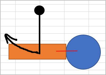
I think that's how many of them work. The dial assembly swings out of the way when not in threading use. I wonder if your center is not quite on center & that's why its catching? Although I can't think of good reason why OK in one direction vs not the other. Both edges of your wheel look the same, not like one is worn. Maybe you can stick a piece of paper in between screw & gear & see how the impression/stain pattern looks?
 

Attachments

  • SNAG-2022-01-29 3.28.43 PM.jpg
    SNAG-2022-01-29 3.28.43 PM.jpg
    16.3 KB · Views: 2

DPittman

Ultra Member
Premium Member
I think that's how many of them work. The dial assembly swings out of the way when not in threading use. I wonder if your center is not quite on center & that's why its catching? Although I can't think of good reason why OK in one direction vs not the other. Both edges of your wheel look the same, not like one is worn. Maybe you can stick a piece of paper in between screw & gear & see how the impression/stain pattern looks?
I wonder if your center is not quite on center & that's why its catching?

Yes I believe that is exactly the reason and tried to articulate above.

One other comment/question on the reversing but did engaging the half nut method...
If you happen to blow it when re-engaging the half nut lever even once then you have to start all over? On my lathe and fine thread lead screw I often miss hitting the mark perfectly. It's not a problem when your threading the traditional way as you can usually disengage and try again before making contact.

Edit
Now I've confused myself....maybe it isn't any different than conventional threading ???
 
Last edited:
Top