• Scam Alert. Members are reminded to NOT send money to buy anything. Don't buy things remote and have it shipped - go get it yourself, pay in person, and take your equipment with you. Scammers have burned people on this forum. Urgency, secrecy, excuses, selling for friend, newish members, FUD, are RED FLAGS. A video conference call is not adequate assurance. Face to face interactions are required. Please report suspicions to the forum admins. Stay Safe - anyone can get scammed.

Making an electric motor adapter for Nema 56C to a B5 D71 Flange

Per the title, I need to make, or have made, a plate adapter to go from a NEMA 56C *inch fractional* frame electric motor housing flange to a B5 D71 *metric* flange. I dont think the Craftex lathe I have access to is a) has a chuck capable of spinning a flange this size, and the RF-30 mill I have access to is beat to shit and isnt very precise anymore, nor do I have a good/accurate way to index things like the bolt holes and spacings required

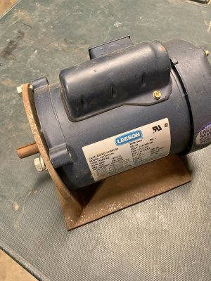
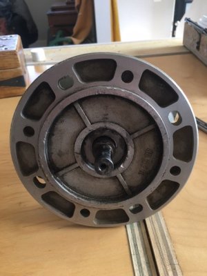
NEMA 56C drawing is attached for reference. Picture of a typical Leeson 56C attached as well.

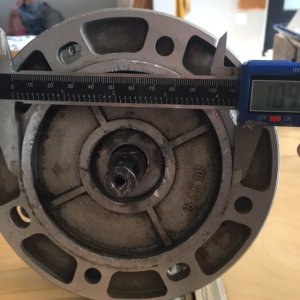
The *KEY* dimensions from the attached 56C pdf drawing needed for the 56C motor facing side of the proposed adapter plate are the BF and AJ measurements for the mounting bolt hole size and spacings AND critically the AK dimension which would need to be a recess in the motor facing side of the adapter. proper positioning of AK, BF, and AJ will ensure that the shaft stays perfectly centered in the flange.

The thickness of the adapter plate is dependant on two key measurements:
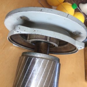
1) The ACTUAL shaft length protruding from the motor housing. The attached PDF has that measurement as 2 1/16", but I have seen NEMA 56C motor (princess auto cheapos for eg) advertised with 1 7/8" to 2".
2) The shaft length that must protrude from the face of the B5 Flange side of the adapter needs to be 1.185". This length is critical as there is a gear that gets installed on the shaft that meshes into a gearbox.


The B5 flange side of the adapter needs to meet D71 metric specs. Please see the attached IEC B5 D Flange dimensions PDF. Note again I need a Frame 71 size. Also important to note that IEC Frame 56 and NEMA frame 56 are NOT the same.

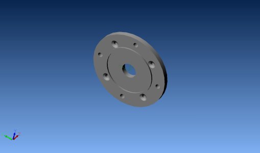
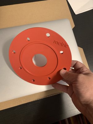
I dont have CAD and my fusion360 skills are non-existent. I did HOWEVER find the a CAD/STEP file for a NEMA frame 56C to IEC B5 *D80* adapter flange at https://grabcad.com/library/56c-frame-to-b5-frame-motor-adaptor . Can this be easily modified to have a D71 face instead of a D80? I've downloaded the .stp file and zipped it and the available redering from grabcad and attached it here for anyone curious.
 

Attachments

  • 38C_DRAWING_56C-3PH.pdf
    38C_DRAWING_56C-3PH.pdf
    117.6 KB · Views: 9
  • leeson.jpg
    leeson.jpg
    115 KB · Views: 3
  • nema56c_to_iec_B5_D80 flange rendering.jpg
    nema56c_to_iec_B5_D80 flange rendering.jpg
    43.3 KB · Views: 3
  • 56CtoB5_adapter.zip
    56CtoB5_adapter.zip
    64.6 KB · Views: 3
  • IEC B5 Flange dimensions.pdf
    IEC B5 Flange dimensions.pdf
    77.6 KB · Views: 2
Yes - I'm curious.

There may be a problem. Here's a drawing of the adapter with B5 D71 dimensions. Note that the AK dimension (a recess in the motor facing side of the adapter) comes very close to the 10mm mounting holes. Also the major OD can not be reduced to 160mm from 200mm per B5 D71 but that should not be a problem.

56CtoB5_adapter 1.jpg


56CtoB5_adapter.jpg
 
 
The major outside dimension of the piece can stay 200 or even 180 I think, I'll have to check the gearbox housing for clearance.

The end application here is a 'made in italy' by 'SCM' https://www.scmgroup.com/en_CA/scmwood/products/edge-banders-squaring-edge-banders.c863 The EU manufacture explains the IEC motor use.

I obtained this machine for essentially scrap value. It is a 'Basic 1' model from the late 90's. Edgebanders of this type are worth a few thousand dollars and up depending on age and condition. I'd like to see if I can get it back into good nick and either use it for the odd jobs I do, or sell it. barring getting it running, I'll part it out and take the 800lb carcass to the recyclers.

Sadly the motor in this one was a) an oversized (a 1hp and not the original 3/4hp) single phase replacement for an original 3 phase unit, b) pretty much cooked field windings and an armature whose shaft ends look like they've been mashed by a 13 year old with a ball peen, and c) as mentioned a IEC metric frame motor. The motor control cabinet wiring has been altered to for the whole machine to run on 220v single phase. The motor Still sorta ran but would start to squeal loudly after 30-60 mins of use and was running excessively hot for a TEFC motor (outer housing measured at 100C or higher during operation), I put new bearings in it as the originals were cooked (FAG 6204 2RS) and it cooked those bearings in about 2 hours of non-loaded bench runtime. I can buy a cheapo 1/2 or 3/4hp TEFC C flange motor for 270 bucks (Princess auto) so its not really worth pursuing a motor rewind/repair IMO.

Here's some pics of the armature mounted in the B5 71 integral housing flange

Oddly the casting letters seems to imply its a D80 flange, but all dimensions clearly show its a D71 flange and it does not appear that its been machined down from a D80. Major diameter, bolt hole spacings and the integral locating ring are all D71 specs.
 

Attachments

  • IMG_3807.JPG
    IMG_3807.JPG
    52.9 KB · Views: 5
  • IMG_3809.JPG
    IMG_3809.JPG
    63.8 KB · Views: 5
  • IMG_3810.JPG
    IMG_3810.JPG
    61 KB · Views: 5
An edge bander… I had a vague idea of those machines. Now I know more..
They are a fairly complicated machine, almost rube goldberg in nature. Requires shop air to drive relay/service triggered air pistons for the trimmers and guillotines. The one I have is entirely analog (well almost) but the new ones are a mix of analog and digital.
 
@calgaryguy hey Chris I could CAD up a drawing for you and we could potentially drill those bolt holes on my mill. If you wanted to draw the part with dimensions on paper and post pictures I expect it would be quick. And then I could see the machine work?
 
Shop air required.
Probably dry shop air and lots of it. are electromechanical solenoids a substitute for air pistons?
 
@calgaryguy hey Chris I could CAD up a drawing for you and we could potentially drill those bolt holes on my mill. If you wanted to draw the part with dimensions on paper and post pictures I expect it would be quick. And then I could see the machine work?
Is the CAD Step file I posted in my original post modifiable? The B5 D80 side (metric side) needs to be modified to the B5 D71 flange dimensions. @eotrfish posted a measured drawing above that I *think* is right?
 
Probably dry shop air and lots of it. are electromechanical solenoids a substitute for air pistons?
Quite possibly? This is probably the most complex machine I've had my grubby hands into. I've been around cabinet shops but they've always been 'Dont touch it except basic maint, we call the vendor for service' situations.

I have it half disassembled for inspection, cleaning, and de-rusting. I'll snap some pics for peoples interest.
 
Last edited:
Is the CAD Step file I posted in my original post modifiable?
Well - sort of

I opened the STEP file and modified the required dimensions. The countersunk holes are boogered in the STEP file so would need to be done correctly. What type of fastener do you plan to use in the 0.385" mounting holes? 82Deg included angle would be appropriate for normal 3/8-16 flat head machine screws. Also the STEP file is done with a mixture of metric and inch dimensions. It would be best if the part was redrawn from scratch - no problem. Let me know if you would like a dimensioned drawing and/or STEP file. Also what thickness would you like the part to be?

56CtoB5_adapter 2.jpg
 
Well if it is to be drilled on my mill the simplest solution is the all the bolt hole positions in X and Y coordinates from an origin, the centre is probably best.
 
Back
Top