Who is running LinuxCNC for their mill? (Other than me).
-
Scam Alert. Members are reminded to NOT send money to buy anything. Don't buy things remote and have it shipped - go get it yourself, pay in person, and take your equipment with you. Scammers have burned people on this forum. Urgency, secrecy, excuses, selling for friend, newish members, FUD, are RED FLAGS. A video conference call is not adequate assurance. Face to face interactions are required. Please report suspicions to the forum admins. Stay Safe - anyone can get scammed.
-
Several Regions have held meetups already, but others are being planned or are evaluating the interest. The Calgary Area Meetup is set for Saturday July 12th at 10am. The signup thread is here! Arbutus has also explored interest in a Fraser Valley meetup but it seems members either missed his thread or had other plans. Let him know if you are interested in a meetup later in the year by posting here! Slowpoke is trying to pull together an Ottawa area meetup later this summer. No date has been selected yet, so let him know if you are interested here! We are not aware of any other meetups being planned this year. If you are interested in doing something in your area, let everyone know and make it happen! Meetups are a great way to make new machining friends and get hands on help in your area. Don’t be shy, sign up and come, or plan your own meetup!
You are using an out of date browser. It may not display this or other websites correctly.
You should upgrade or use an alternative browser.
You should upgrade or use an alternative browser.
LinuxCNC
- Thread starter jcdammeyer
- Start date
Nice to meet you in person too. And you got to watch my probe in action.
Alas, that won't be possible anymore. I tried out a different routine. Couldn't get to the ESTOP fast enough.🙁

Alas, that won't be possible anymore. I tried out a different routine. Couldn't get to the ESTOP fast enough.🙁
Not repairable either. Too many bent pieces.

Yes, I am running Linux cnc
Good to know. What user interface? AXIS or something else?Yes, I am running Linux cnc
New probe will ship July 14th.
New in Vers PR v8
Pin-ball contacts now made of tungsten carbide
Unidirectional repeatability < 0.002 mm
Tip free travel in XY ±7 mm, in Z -4 mm
I don't think the -4mm Z travel would have made a difference. Even though I said I'd leave this alone for a while I think I may add some diagnostic statements to the code to see why it took off the way it did at what appeared to be full speed.
Dan Dubeau
Ultra Member
I will be attempting a linux cnc conversion of a small CNC training lathe over the winter.
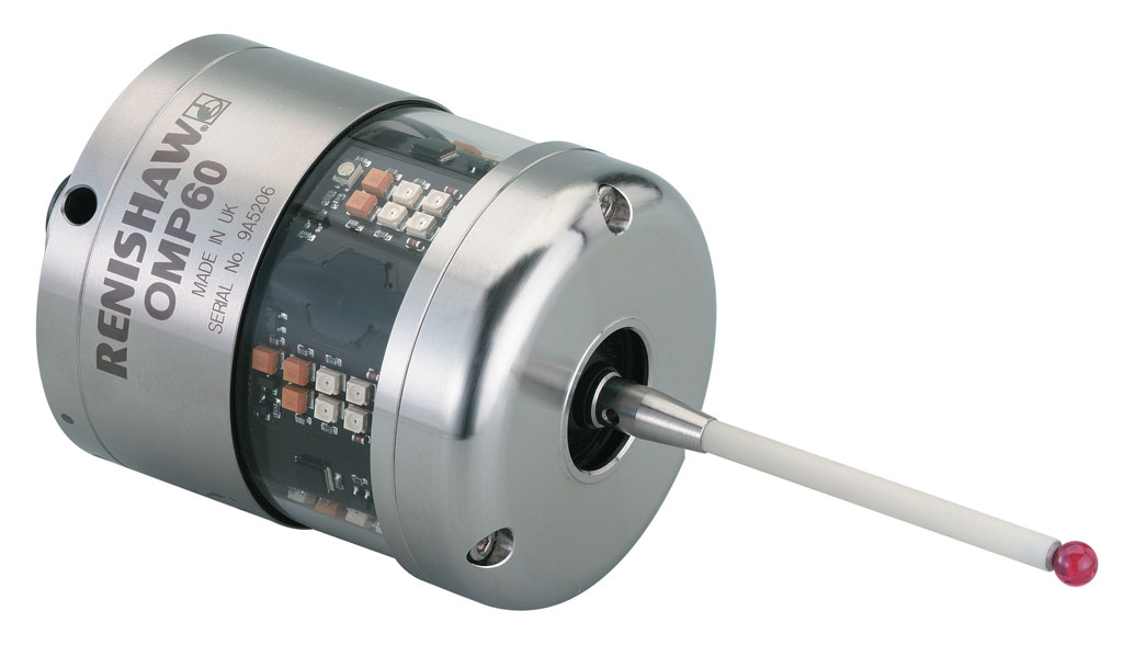
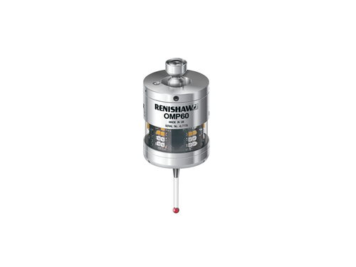
On the renishaw probing system the probe tip is a pretty long *85mm ceramic unit. I've crashed it once and broke the probe. No damage to the probe head fortunately. Is there an option on that probe for a long ceramic one? It gives you a lot more length (3 inches) to hit the stop when crashing. This one below is similar.
In this case I was probing the two 1-2-3 blocks set for 4" since my previous demo, where the values were wrong turned out to be for the 2"+3" arrangement. Since the distance to probe in this case is 0.25" I had it set just above the blocks. As the crashed photo shows, one block was bounced away and the second did all the damage.
The cable is a magnetic connection and it's set up as NC. So remove the cable or shift the probe and it reports touched. It should have stopped it. Normally if I bump the probe during any move it stops with an error. So in reality this shouldn't even have happened. And in fact the system finally stopped due to a following error when it couldn't go down any further.
The new probe with shipping ends up just over $198Cdn and will ship out on the 14th via post. So should have it by the end of the month. Meanwhile I have to put a jumper with a switch in place to fake out the probe so I can test the software.
Not sure I'd be happy damaging one of the Renishaw ones.
 www.machinetoolproducts.com
The cable is a magnetic connection and it's set up as NC. So remove the cable or shift the probe and it reports touched. It should have stopped it. Normally if I bump the probe during any move it stops with an error. So in reality this shouldn't even have happened. And in fact the system finally stopped due to a following error when it couldn't go down any further.
The new probe with shipping ends up just over $198Cdn and will ship out on the 14th via post. So should have it by the end of the month. Meanwhile I have to put a jumper with a switch in place to fake out the probe so I can test the software.
Not sure I'd be happy damaging one of the Renishaw ones.
Renishaw OMP60 Optical Transmission Part Probe for Machining Centers
Value Added Distributor
www.machinetoolproducts.com
Alright. Although the new probe will probably be here in month I really don't want to forget everything and have to start over. But I need a normally closed probe that is held in the spindle so when the knee comes up it switches open.
So I made one.

And here's the back of it.

The heads were a bit big on the 6mm screws. Should have made them 5mm. So I used the Unimat DB200 to just make them a tad smaller in diameter.
The switch button is on the spindle center line... more or less.
So I made one.
And here's the back of it.
The heads were a bit big on the 6mm screws. Should have made them 5mm. So I used the Unimat DB200 to just make them a tad smaller in diameter.
The switch button is on the spindle center line... more or less.
This thread really belongs over at the CNC subject with the DRO. Maybe it should be moved there?

 canadianhobbymetalworkers.com
BTW. I found one of the two problems. I won't go into the general G-Code details but here's a summary.
First some poorly documented code.
; Save current Z position
#<z>=#<_z>
Seriously? That's like saying
MyCopyofPi = 3.14; // Put 3.14 into MyCopyofPi.
This kind of crap documentation is everywhere unfortunately. It's obvious what's been done but not why.
Say we had something in the vise that extended just above the jaws and we machined a slot in it starting at Z=0.000 and to a depth of 0.200". We went down so Z became bigger.
Now we clamp a large block in the vise and it extends 2" above the jaws. We also want to put a 0.2" slot in that so first we have to establish the top as Z=0.000. We use the probe for that. Knee goes further down and Z gets bigger. What's saved when we're ready to touch off, Z is at 2.2" and that's what's saved.
The touch probe detects the surface of the new block and sets our Z origin to Z=0.000 and we're ready to cut the slot. But first the tool setting code does this:
G0 Z#<z>
Full speed to the saved Z position which was 2.2" so the knee heads down very quickly away from the touch probe.
Next we want to cut a small part in the vise again. It's only 0.5" above the jaws and we want to cut another slot 0.2" deep. Tool change to the probe and move it within 0.25" of the surface as before. We've really moved the knee up 1.75" to bring the shorter piece in the vise up to the probe and of course closer to the spindle is a negative move so the value saved is -1.75".
The touch probe detects the surface of the new block and sets our Z origin to Z=0.000 and we're ready to cut the slot. But first the tool setting code does this:
G0 Z#<z>
Full speed to the saved Z position which was -1.75" so the knee heads up very quickly towards from the touch probe which was sitting 0.1" above after finishing the probe.
Bang.
So I changed the code to do this:
O2 if [#<z> GT 0.000]
G0 Z#<z>
O2 else
(PRINT, <z> is negative, would move into probe. Don't move at all)
O2 endif
I'm not sure what the thinking was behind saving Z and then restoring it.
The original screen has a checkbox for set origin. So if I probe the mill table with the checkbox set then the table is now Z=0.000.
Next if I uncheck the box and probe a part I set on the table it would probe and stop 0.1" above what it probed. It doesn't change the Z origin so now I know the part is say 2.5" high because the DRO shows -2.6"
I guess.
Interfacing LinuxCNC to a Touch-Probe and Tool-Setter
About a year and a half ago my tool setter arrived so I decided to add it along with my touch probe to the PSNG Touch Screen. Last time I did anything with it was last January. Although I thought I'd done a good enough job documenting things it turns out I didn't. Can't remember how to use it...
BTW. I found one of the two problems. I won't go into the general G-Code details but here's a summary.
First some poorly documented code.
; Save current Z position
#<z>=#<_z>
Seriously? That's like saying
MyCopyofPi = 3.14; // Put 3.14 into MyCopyofPi.
This kind of crap documentation is everywhere unfortunately. It's obvious what's been done but not why.
Say we had something in the vise that extended just above the jaws and we machined a slot in it starting at Z=0.000 and to a depth of 0.200". We went down so Z became bigger.
Now we clamp a large block in the vise and it extends 2" above the jaws. We also want to put a 0.2" slot in that so first we have to establish the top as Z=0.000. We use the probe for that. Knee goes further down and Z gets bigger. What's saved when we're ready to touch off, Z is at 2.2" and that's what's saved.
The touch probe detects the surface of the new block and sets our Z origin to Z=0.000 and we're ready to cut the slot. But first the tool setting code does this:
G0 Z#<z>
Full speed to the saved Z position which was 2.2" so the knee heads down very quickly away from the touch probe.
Next we want to cut a small part in the vise again. It's only 0.5" above the jaws and we want to cut another slot 0.2" deep. Tool change to the probe and move it within 0.25" of the surface as before. We've really moved the knee up 1.75" to bring the shorter piece in the vise up to the probe and of course closer to the spindle is a negative move so the value saved is -1.75".
The touch probe detects the surface of the new block and sets our Z origin to Z=0.000 and we're ready to cut the slot. But first the tool setting code does this:
G0 Z#<z>
Full speed to the saved Z position which was -1.75" so the knee heads up very quickly towards from the touch probe which was sitting 0.1" above after finishing the probe.
Bang.
So I changed the code to do this:
O2 if [#<z> GT 0.000]
G0 Z#<z>
O2 else
(PRINT, <z> is negative, would move into probe. Don't move at all)
O2 endif
I'm not sure what the thinking was behind saving Z and then restoring it.
The original screen has a checkbox for set origin. So if I probe the mill table with the checkbox set then the table is now Z=0.000.
Next if I uncheck the box and probe a part I set on the table it would probe and stop 0.1" above what it probed. It doesn't change the Z origin so now I know the part is say 2.5" high because the DRO shows -2.6"
I guess.
Mine is supposed to do that too. But I read somewhere that it can also be disabled. I'm wondering if it's active for G01 moves but not for the G0's.John - I think G0 moves with the probe installed are terrifying.
Somehow in the renishaw code if the probe is activated unexpectedly during a move it stops the movement immediately. Like an interrupt but I have no idea how they do that with gcode.
It's one of the things I'm chasing down now..
I found another oops today too. I ran the probe software with the probe installed but forgot to do the tool change to select T99. It did tell me that the tool wasn't loaded. And then the knee headed straight up so the subroutine that does that has a similar fault to the first one that killed my probe.
But, although no photographs yet... (or movies)... I have 3 G-Code files now that do the pocketing, center drilling and 1/8" hole. Yes, it could be done with a forstner bit and drill bit on the drill press.

What's cool about it is the pocketing and center drill programs just ask for the tool and then zoom over at G00 speed and do the work.
The Drill 0.125 program asks me to load the tool which normally would consist of installing the TTS drill chuck and then the drill bit. Then I click on OK and it moves over to the Tool Setter and heads on down. Touchs off. Then up and over and drills the hole. Top of the drill bit is exactly where it's supposed to be.
So this is all going the way it's supposed to.
My replacement probe arrived today. I'm continuing this topic over at the original one:
canadianhobbymetalworkers.com
Interfacing LinuxCNC to a Touch-Probe and Tool-Setter
About a year and a half ago my tool setter arrived so I decided to add it along with my touch probe to the PSNG Touch Screen. Last time I did anything with it was last January. Although I thought I'd done a good enough job documenting things it turns out I didn't. Can't remember how to use it...
I bought one of these over the weekend. It was delivered Monday and today I managed to get it all working.
The hardware description and what it can do or connect to is here:
I initially tried the Raspberry Pi4 running LinuxCNC with the MESA 7i92H. The only stange issue is the Touch Screen PSNG is supposed to be for the 1200x800 screen but some of that is cut off. Not sure why.

The other issue is occasionally the screen pops into power saver mode. ie. Screen goes blank. Then comes back. I changed to the standard PI power supply instead of using the one from the screen and I think that fixed it. I'm guessing the 5V output is right on the edge and if it drops the HDMI output ceases and the touch screen says "OK. NO video. I go blank".
The touch part does work. Quiet well.
Next I connected up the BeagleBone Black. I edited the photo as for some reason my phone added a lot of green while in real life it wasn't. The Beagle was never set up to use the PSNG screen so it's not one of the tabs. Again, once I connected the switch assembly to the DB-25 I was able to take it out of reset and the buttons worked with my fat fingers.

Finally after a bunch of work removing the panel on the side I managed to get the Lathe Screen working and of course I forgot to take a photo of that. The Touchy inteface requires a bunch of dedicated external switches for it to function correctly including an MPG for jogging. Since I didn't have the I/O or the connections I left it at just being able to touch the buttons on the screen and watch it do things.
This is exactly what it looked like on the 10" Touch Screen.
So what's next? Because the PI4 screws to the back of the panel and the two 3D printed stands hold it up the next step is to mount the MESA 7i92H and the break out boards onto a panel along with power supplies and any other issues. Then maybe revisit the Touchy Screen set.
And possibly 3D print a cover to go around this so it can hang out on an arm above my Gingery Lathe.
The hardware description and what it can do or connect to is here:
I initially tried the Raspberry Pi4 running LinuxCNC with the MESA 7i92H. The only stange issue is the Touch Screen PSNG is supposed to be for the 1200x800 screen but some of that is cut off. Not sure why.
The other issue is occasionally the screen pops into power saver mode. ie. Screen goes blank. Then comes back. I changed to the standard PI power supply instead of using the one from the screen and I think that fixed it. I'm guessing the 5V output is right on the edge and if it drops the HDMI output ceases and the touch screen says "OK. NO video. I go blank".
The touch part does work. Quiet well.
Next I connected up the BeagleBone Black. I edited the photo as for some reason my phone added a lot of green while in real life it wasn't. The Beagle was never set up to use the PSNG screen so it's not one of the tabs. Again, once I connected the switch assembly to the DB-25 I was able to take it out of reset and the buttons worked with my fat fingers.
Finally after a bunch of work removing the panel on the side I managed to get the Lathe Screen working and of course I forgot to take a photo of that. The Touchy inteface requires a bunch of dedicated external switches for it to function correctly including an MPG for jogging. Since I didn't have the I/O or the connections I left it at just being able to touch the buttons on the screen and watch it do things.
This is exactly what it looked like on the 10" Touch Screen.
So what's next? Because the PI4 screws to the back of the panel and the two 3D printed stands hold it up the next step is to mount the MESA 7i92H and the break out boards onto a panel along with power supplies and any other issues. Then maybe revisit the Touchy Screen set.
And possibly 3D print a cover to go around this so it can hang out on an arm above my Gingery Lathe.