• Scam Alert. Members are reminded to NOT send money to buy anything. Don't buy things remote and have it shipped - go get it yourself, pay in person, and take your equipment with you. Scammers have burned people on this forum. Urgency, secrecy, excuses, selling for friend, newish members, FUD, are RED FLAGS. A video conference call is not adequate assurance. Face to face interactions are required. Please report suspicions to the forum admins. Stay Safe - anyone can get scammed.

LED info for mill light

PeterT

Ultra Member
Premium Member
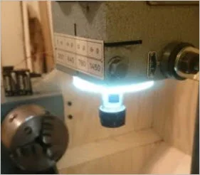
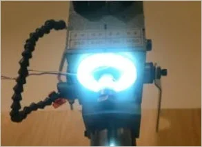
Can anyone point me in the right direction. I want to make an LED light for my mill similar to these aftermarket ones. I am tired of fighting with my gooseneck lamp coming in from the side. The magnet dos not hold well on the cast iron & I'm always reaching in the same area to lock the head or touch the DRO. I do like the LED replacement bulb though, it runs cool & I'm not worried about the occasional fling chip or splatter.

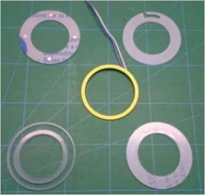
I like the idea of a ring that is attached to underside of mill head & lights always pointing down at the work vs side glare in my eyes. But don't need it tied to the spindle housing itself. I was thinking more of a frame that holds LED's, could be circular donut or maybe even 4"x4" square, just attached to underside.

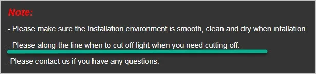
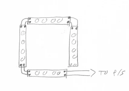
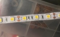
- how do I work with fixed length LED strips like I see them typically sold like 1m or 5m continuous lengths? Can I cut the strip into say 4 segments say 5 LED's per segment to make a square shape mounted on a plastic frame or substrate? Then what, do I solder interconnects to bridge the 90-deg cut corner?

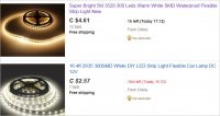
- I have 110v available, what do I need to power the LEDS? I see some kits include DC power adapters but are they sized specifically to the fixed length of LED strip they are packaged with? (ie. no longer suitable for shorter lower LED count?
 

Attachments

  • SNAG-4-22-2017 0003.jpg
    SNAG-4-22-2017 0003.jpg
    45.1 KB · Views: 9
  • SNAG-4-22-2017 0002.webp
    SNAG-4-22-2017 0002.webp
    9.2 KB · Views: 6
  • SNAG-4-22-2017 0001.webp
    SNAG-4-22-2017 0001.webp
    7.4 KB · Views: 6
  • SNAG-4-22-2017 0000.webp
    SNAG-4-22-2017 0000.webp
    5.9 KB · Views: 7
A reputable supplier will tell you how many milliamps per meter. You can then buy their sized power supply or use any quality source. Most of the strips are 12VDC. I've used old 12DC wall warts in the past. I've used Eco Lighting Solutions Calgary in the past: Not the cheapest, but very helpful and knowledgeable.
 
This video is giving me some hints. Its a UK firm so leery about the PS with their Whitworth thread voltage :) Maybe similar to the ebay/ali kits I see. When you see how he is cuts a shorter segment & then attaches a pigtail, I'm wondering of couldn't just cut myself some multiple strips, re-orient them how I like & jumper the +/- contact pads like sketch?


Attachments

  • led strip segment.webp
    led strip segment.webp
    20.4 KB · Views: 3
Here's another vid. Around min 5 he hooks up the ends like I was wondering. Its obviously a much bigger fixture (which has be thinking I'd like one!) & interesting control do-dad to vary output.
 
The strips are marked where they can be cut, I don't recall offhand how many leds there would be per portion but it has to be no more than 4 or 5 for a 12 volt strip. If you don't want to solder there are clips you can buy like these from be
http://www.be-electronics.com/product_p/55-740-0.htm
They are sized to match the width of the strip, I had to order from China to get ones to match the strip I have.
 
I'm totally fine to solder. It was more the hookup I was not clear on. But it looks like they are kind of intended to be configured this way. So if I bought a 1 meter strip kit but used less lineal total in reconfigured/rejoined, would it still work ok on that PS or is PS kind of matched to that length?
example saw this on ebay
http://www.ebay.ca/itm/1M-20M-RGB-5...hash=item27e74cc884:m:m-b-4mB0LSahWIqt5-jyN9g

What did you build or use yours for John?
 

Attachments

  • SNAG-4-22-2017 0004.jpg
    SNAG-4-22-2017 0004.jpg
    41.8 KB · Views: 3
Mine is like this. https://www.amazon.ca/Flexible-Non-...UTF8&qid=1492958911&sr=8-4&keywords=Led+strip
and is a bit simpler than the RGB one you are looking at. You can cut mine every 3 leds. There are only two connections to solder, an RGB strip will have additional connections for control signals.

The supply voltage is the same no matter how long of section you are using. I haven't used mine for a project yet.
 

Attachments

  • IMG_2579.JPG
    IMG_2579.JPG
    354.3 KB · Views: 5
PeterT, this is what I used as a "starter kit" for my spindle light on my BR2J2 (I bought it on one of their 25% off sales):

www.princessauto.com/en/detail/led-drill-press-work-light/A-p8381113e

I tore it all apart and used only the components that I needed. I made a metal mounting ring from some scrap sheet steel and welded a little post on it so I could use an existing fixture on the mill head.

Here is the kit
DSC03123.JPG

Here are the components: blue seal, opaque diffuser, white LED internal mounting ring, black external cover/screw mount. You can also see the ON/OFF switch and the power supply
DSC03124.JPG

Here it is after modification and re-assembly; it is upside down, but you can just see the metal ring and post that replaced the original plastic top cover and clamp screws (see above pic)
DSC03125.JPG

Here it is mounted on the mill; you can see the metal ring and mounting post. The spindle fits perfectly through the 1 5/8" hole in the ring light. (Yes, I know, shitty stick welding job - I do not have a MIG or TIG yet...)
DSC03127.JPG

Let there be light...
DSC03128.JPG

For now I left it with the 14 LEDs it came with. I may add more in the future for even more light - there is enough room inside the ring to do that.

The light does not move down with the spindle; therefore, I do get a shadow cast when the spindle extends or with large tools installed. It is a very uniform illumination of the work.

Cheers, Rudy
 
So if I bought a 1 meter strip kit but used less lineal total in reconfigured/rejoined, would it still work ok on that PS or is PS kind of matched to that length?
Yes, PS would work fine. There is nothing you would have to do/or be worried about. Your circuit schematic looks fine as well. Just hook + to + and - to - and away you go.
 
Thanks Rudy. I didn't even think to look at PA. Interesting. So by their description I'm guessing the ID of housing donut is ~ 3-15/16" Quick, tool-free thumbscrew attachment fits 1-5/8 to 3-15/16 in. range

I'm going to have a closer look under my mill for mounting real estate now that I see your pics. The circular pattern makes sense on one level, but the shadow cast is kind of what I was wondering if a square/rectangular array might help with. Cost will be about the same. Actually those photo panel array examples I posted have me thinking about mini versions like my scroll saw or whatever. They are a broader light source, not spotty. That's the issue I have on my scroll saw, something is always in the shadow.
 
LED Christmas lights use 110v with resistors and ((first pic not resistors?) many different combinations used across many brands) ) off hand each string has 75 diodes and the string is rated to draw 0.04A and 4.8W.
Testing a single bulb requires 3V, [email protected] batteries to light (custom lights with 3 diodes each)
The second picture is 6 diodes (2bulbs) running off 110V (the small "block" has the resistor but I don't have one opened to identify it.

I think RadioShack might still sell individual diodes etc to DIY But I'm just to show no need for adapters to adapt adapters. diodes in a 12V system are the same as the 110V

Also having chopped up a strand to do this I've got bits laying around including white lights and the mystery resistor if you would like image.jpgimage.jpg
 
Yes, of course PeterT: the ID of the ring is 3-15/16" not 1-5/8" as I stated.

I use the ring light as a general "area" light. For detailed illumination I still us a spot light/flash light.
 
I'll throw some technical information about LED's in here to try to confuse everybody:

LED - Light Emitting Diode - Actually almost all diodes are light emitting. LED's are just diodes that are optimized to create light.

Firstly, LED's are diodes. When current goes through them in the forward direction (conventional current from the anode to the cathode - the anode is positive, the cathode is negative) there will be a voltage drop across the junction and light will be emitted roughly in proportion to the current. The voltage drop is nearly constant with current.

So when you apply a forward DC current to an LED, there will be a nearly constant voltage drop across the diode. Regular diodes have a forward voltage drop in the .7 to .9 volt range (they tend to emit some far infrared internally). Infrared LED's are in the 1-2 volt range. Red - about 2.2V, Green a bit higher, blue and ultraviolet LED's are in the 3.5 - 4.0V range. The color of the light (frequency) is generally dependent on how high the forward voltage drop is. The forward voltage drop is dependent on what the diode is made of.

White LED's are actually blue or near-ultraviolet LED's with phosphor that absorbs some of the blue/UV and emits it as yellow (yellow is actually red and green light). The results is red, green, and blue light that human eyes perceive as white. The phosphor is why white LED's look yellow when they are off.

If you take a "white" LED and put 3V across it, almost no current will flow. As you approach the forward voltage drop (about 3.5 - 4V), the current will increase very rapidly. As the current increases, the emitted light will increase in proportion. As the current increases, there is heat generated at the junction, and it will quickly destroy the diode. At less than 4.5V you will probably let out the magic smoke. It is important to limit the current through the LED to be less than what the diode can handle.

The easiest way to limit the current is with a simple resistor. If you put three 3.5V LED's in series, they will drop 10.5V. If you then add a resistor, and feed it with 12V, the current will be limited by the resistor. Use the standard V = I x R to determine the resistor value If you want to limit the current to 100mA (0.10A), using R = V / I, you get (12 - 10.5) / 0.1 which is 15 ohms. So, a 15 ohm resistor will limit the current through the three series LED's to 100Ma. Each LED will have 100mA flowing through it (they are in series), and will produce the amount of light that diode produces from 100mA.

In this case most of the power is dissipated by the LED's and only a little by the resistor (10.5V across the LEDs, and 1.5V across the resistor. The resistor just turns the wasted power into heat, so if it tries to dissipate too much power it will burn up.

That is why most small LED strips consists of 3 LEDs' and a resistor when fed by 12V. This becomes quite sensitive to input voltage since if you raise the input voltage to 13.5, the voltage drop across the resistor increases to 3V, which would double the current to 200mA from 100MA.

Much fancier setups will use an active switching circuit to control the current through the LED's. That is what you will find inside of most really bright LED fixtures.

LED's are not good at resisting voltage in the reverse direction. All diodes have a reverse breakdown voltage. If the voltage across the diode exceeds the reverse breakdown voltage the diode will begin to flow current in the reverse direction. That is usually catastrophic for the diode (zener diodes are diodes that are designed to do that). The magic smoke will usually be released. The reverse breakdown voltage is not usually even published by the manufacturer of the diode since the LED should generally never have a reverse voltage applied across it.

That brings me to LED Xmas lights that run off of 120VAC. There should be a regular diode (with a 200+V reverse breakdown rating) in series with the LED's to protect them from high reverse voltages. I've never really looked at how the cheapie AC strings are wired, but I would guess that they would be split into two substrings, each wired in a different direction. One would light on one half of the AC cycle, the other on the other half of the cycle. There could be 30-40 "white" LED's per substring, with a resistor to provide current limiting.

If you are using LED's to light up a machine be careful of the LED's flashing. LED's are very fast and if their power comes from the AC line, they will flash 6o times a second. If they are powered by a decent12V DC supply, there will be capacitors in the supply to smooth the DC so there is no flashing.
 
Thanks John. I think I digested most of what you said. This is why I was asking - if I buy a 1 meter strip & a matching PS (one of the those el-cheapo 110vac>12vdc or whatever they decide is appropriate output voltage). But now I cut the 1.0 meter into 4 single strip segments for my rectangular shape, wire the ends in series, now it adds up to only say 0.4m. Would I be potentially exposing the LEDs to excessive current? Do the little black thingy's in the strip and/or the PS somehow compensate to fix things? I've seen some guys put a knob (potentiometer?) which I assumed was dimming, but maybe that is their way to add make-up resistance?

I had a bailout plan in mind, not sure if its feasible until I lay it out. But for example, 4 double rows of LEDS 12cm length = 4 x 2 x 12 = 96 cm (close to 100 cm ... you see what I mean).
 
I believe behind the shrink wrap in my first pic (the "large" block) is 2 if theseimage.jpg (Ignore the value of it)
Designed to allow electrons one way only flow (confirm?)
We have had slight pulsing this model year after decreasing the resistance from previous models, the result was brighter lights and not everyone can tell they flash but hey now I know better why they do.
 
It is not a problem to cut the strip into segments (where it is designed to be cut), and wire them in parallel. It does not matter if they are wired as a star or as a long strip. As long as the + connection points are all wired together, and the - connection points are wired together and connected to the + and - terminals on the power supply.

When they are in a long strip they are already wired in parallel.

A 12V switching wall -wart would work fine. It just needs to be able to put out enough current to drive all the LED.s

The strips are usually marked as to where they can be cut. In "image_2579.jpg" posted by Johnwa, it is clear as to where they can be cut - there are small scissor marks. The black thingies are marked with 151, which means 150 ohms (15 x 10 to the power of one, or 15 x 10). There are three LED's and three resistors in each segment. I would bet that each LED is in series with one of the resistors. The resistors would then limit the current in each LED to about 50mA (0.050 A). With three LED's, each segment of the strip would draw about 150mA. If you used ten of those short strips, that would draw about 1.5A. You should then have a wall wart rated for 12V and about 2A.

Switching converters are much better to use than a transformer based one. How to tell the difference: A transformer based wall-wart will be quite heavy and large. A switching based one will be small and light, and likely rated for 100-250V, while the transformer based one would be rated for 120V only. With a switching wall-wart, there would be no concern about the LED's flashing.

Your configuration is electrically the same. The black-thingies are almost certainly the resistors that do the current limiting.

Edit: Fix some typos.
 
Last edited:
Bofobo: That is a diode. It will only allow current to flow from the black end to the end with the silver stripe. The two of them are separating your string of LED's into two sub-strings. Note that in your original image, that the black diodes are connected in opposite directions. On one half of the AC cycle current will flow though one sub-string of LED's back to the other AC wire. In the other half of the cycle, current will flow to the other sub-string.

As I mentioned before, LED's are diodes but they cannot deal with significant reverse voltages. The conventional diode is added in there (probably rated at 200V reverse or more) to protect the LEDs from the other half of the AC cycle that would reverse bias them.

This will cause all of the LED's to flash 60 times per second, and any LED will only be on for less than half of the time. Rapidly moving the LED's (or your eyes) will confirm the flashing.

You mentioned "electrons". They actually flow from the striped end to the non-striped end! That is electron flow.

When I mention current flow, I am referring to what is called "conventional current". Conventional current flows from + to -. That makes sense. That is what everyone is used to. The electrons actually flow in the other direction.

The terminology for current and positive and negative was established way back before "they" knew much about electrons. It turns out that electrons have a negative charge, so the electrons actually move in the opposite direction of conventional current. You can now forget that. It only makes a difference if you are looking to the physics of how a semi-conductor junction works. Just always think about conventional current that flows from positive to negative. It works fine that way. Forget that the electrons actually go the other way.

Except, or course, if you are talking about TIG welding. There is more heat transfer with a negative electrode. Although the conventional current is flowing from the work-piece into the electrode, the actual electrons are flowing from the electrode to the work. The electrons create more heat in the work-piece when they are smashing into it. With electrode positive, the electrons are leaving the work (helping to break up aluminum oxide in the process), and smashing into the electrode which tends to get very hot and melt.

Edit: Fixed typos and added information about welding.
 
Last edited:
Back
Top