• Spring 2024 meetup in Calgary - date Saturday, April 20/2024. discussion Please RSVP Here to confirm and get your invitation and the location details. RSVP NOW so organizers can plan to get sufficient food etc. One week to go! More info and agenda
  • We are having email/registration problems again. Diagnosis is underway. New users sorry if you are having trouble getting registered. We are exploring different options to get registered. Contact the forum via another member or on facebook if you're stuck. Update -> we think it is fixed. Let us know if not.
  • Spring meet up in Ontario, April 6/2024. NEW LOCATION See Post #31 Discussion AND THE NEW LOCATION

Lathe Stop

PeterT

Ultra Member
Premium Member
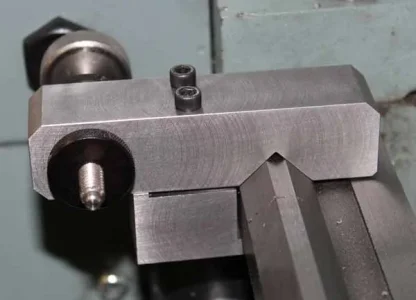
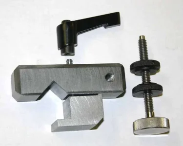
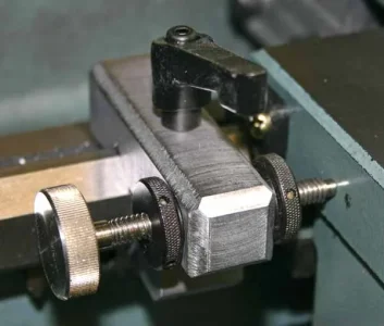
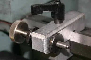
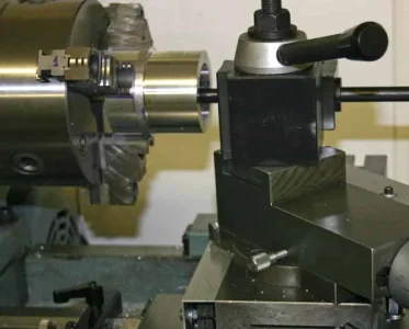
I actually made this accessory quite a while ago but snapped a pic for another purpose. Its useful when you want the carriage to come to a repeatable X position stop as you are removing stock in progressive passes. There are many variations out there, most are more functional than mine. Some have a rotating detent hub with different pin lengths so you can have a series of stops. Note, these are not meant to be contacted under power! You just gently contact the pin by hand, back out, reset in feed & repeat.

In hindsight I'd do things a bit different, so maybe give you some considerations for your own:

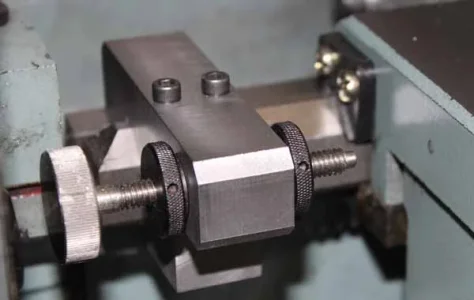
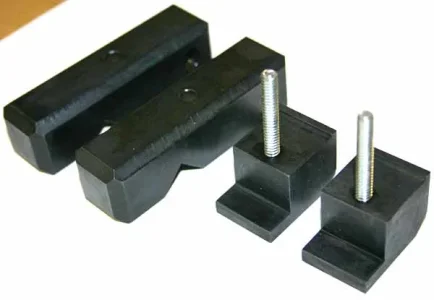
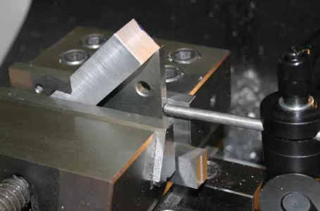
- I chose the threaded thumbscrew thinking I could machine the first pass to desired X dimension, then snug the screw to contact, tighten the nuts & then its nicely locked in position. That aspect is fine, but now I worry that if I ever fell asleep at the switch & contacted under traverse power, it would be a bad day: shear the lead screw pin, damage gears, maybe scrape the ways if it mangled the stop... So a maybe a better solution is a smooth pin that is clamped in position. Chances are better if it contacts that, it would push the pin & give you a split second of last minute save. But lets not think unhappy thoughts! Come off the power early with a safe margin & in-feed by hand.

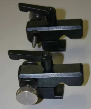
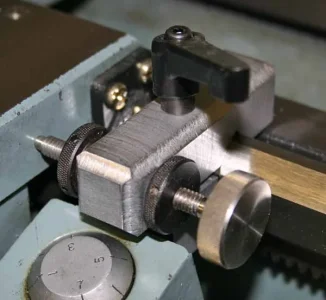
- My 2 socket cap screws for clamping were just handy. But I would find one of those quick release, spring loaded adjustable clamp thingy's & save myself looking for yet another tool

- maybe make it adaptable to a cheapo plunger dial indicator stem. Its not really the same thing as a 'stop' but that's handy if you want to hit the same dimension within a thou.
 

Attachments

  • IMG_0789_edited-1.jpg
    IMG_0789_edited-1.jpg
    35.9 KB · Views: 35
  • IMG_0787_edited-1.jpg
    IMG_0787_edited-1.jpg
    35.1 KB · Views: 35
L

Louis Dusablon

Guest
Nice work indeed, maybe my next work project as I don't have a stop on my lathe
 

PeterT

Ultra Member
Premium Member
Oh no. Not another lathe stop post! Ever have one of those jobs where you estimate an afternoon... and 2 days goes by?

I've had some turning operations on the lathe where I've had to go back & forth between two X positions until proper depth. Imagine a wide internal groove inside a bore. Its not a big deal, I used to stop on the left side where my single one was mounted & then unwind to the right up to a specific dial setting. But I'm inherently lazy & wanted something that would stop on either side. And mostly prevent an over-cut oops by over-rotating the dial or losing track of position (which happened).

My #1 stop above clamped secure & worked well so I thought just clone it & make another. But turns out the bar length would not fit some of the lathe features on the right side of the apron, it had to be shortened & some bevels. I also thought it would be nicer to have one of those quick release clamps. Half turn unclamp, slide to position, half turn clamp, no reaching for hex keys. Also these handles are sprung so you can pull up a bit further & rotate to some other convenient détente position so its out of the way. My first one had two 8-32 cap screws. I used 2 mostly to keep the upper/lower parts aligned so the clamp doesn't want to rotate out of position as it slides along the V. So I thought this version would require a dowel pin > hole or something because the assembly is free to pivot on the 10-24 handle stud. But turns out I got the parts fitting pretty well, they stay aligned to the bed because the gap is quite small & don't really rotate out of position. So hear it is, hopefully self explanatory. Any questions fire away.
 

Attachments

  • IMG_5629_edited-1.jpg
    IMG_5629_edited-1.jpg
    37.2 KB · Views: 16
  • IMG_5626_edited-1.jpg
    IMG_5626_edited-1.jpg
    33.7 KB · Views: 17
  • IMG_5625_edited-1.jpg
    IMG_5625_edited-1.jpg
    36.8 KB · Views: 13
  • IMG_5621_edited-1.jpg
    IMG_5621_edited-1.jpg
    47.8 KB · Views: 13
  • IMG_5620_edited-1.jpg
    IMG_5620_edited-1.jpg
    44.1 KB · Views: 12
  • IMG_5619_edited-1.jpg
    IMG_5619_edited-1.jpg
    26.6 KB · Views: 13

Tom Kitta

Ultra Member
This is a slight variation of what I made - alas I sold it with my old lathe. Guess I have to make a new one. Mine had a V cut in a large block of steel and two screws holding it on the side. There was also a stop screw just not as fancy as this one. I didn't make anything to hold it from underneath - maybe there was a slight rise when tightening it but since the raise is vertical and measuring surface is horizontal I don't think it's a big deal.
 

PeterT

Ultra Member
Premium Member
The stops are handy. I used the single/left one a lot during roughing too. I set it say 0.020" over finish dimension, travers, disengage, just kiss the stop, backup up & repeat. One thing about these stops, especially if the are well clamped. You don't want to fall asleep at the switch & hit it under power or bad things could happen to the lathe bed. Also be mindful of any particles on the Vee or you will basically clamp that grit down.

Full disclosure: I bought the 1/4-20 thumbscrew & jamb nuts. Could have made them too I guess but.. fiddly bits, time better spent on other things :)
 

Tom Kitta

Ultra Member
Some lathes have a disengage setting for the stop to hit - I think that is a great idea - prevents bad crashes.
 

PeterT

Ultra Member
Premium Member
More pics & apprentice notes. I haven't had to make many parts with V notches but I've learned not to underestimate them. If you have any tips, pass them on.

- I left my stock edges as close to 90-deg sharp as possible ie. no exaggerated file edge chamfering. This way when the stock was set at angle in vise, I can indicate laterally in one direction from the corner & vertically from the datum so the corner notch facets are known reasonably accurately. The other method I considered was just mill the V's wherever, leaving excess stock on ends, then align V's & trim bar to common dimension later. But I figured I still have to mill a predetermined amount of X & Y material to make the notch facets equal sided, so why not go for glory & try & accomplish that in 1-shot by dimensioning off an edge. Hope this makes sense. One of those easy to draw, maybe not so easy to make parts :)

- still not sure this was correct procedure or not but seemed to work better than my Owie incident. First I established the bottom facet by end milling to depth. Then I traversed across the other V side in progressive depths leaving 0.005" or so for final finish pass with EM side. This 2-step method minimizes EM cutting from both its bottom & side simultaneously in the corner. I learned (painfully) it can grab & bad things happen. None of this was climb milling, that's just asking for it. My EM was not ideal for finishing & this is just crappy CRS so I blued & finished with a file. Here is start of that operation. It highlights all the steps & spirals. It actually looks better in real life. Mostly I just wanted it to be smooth & reasonably accurate, it clamps to the lathe V.
 

Attachments

  • IMG_5577_edited-1.jpg
    IMG_5577_edited-1.jpg
    38.4 KB · Views: 11
  • IMG_5569_edited-1.jpg
    IMG_5569_edited-1.jpg
    36.9 KB · Views: 11
  • IMG_5568_edited-1.jpg
    IMG_5568_edited-1.jpg
    157.4 KB · Views: 11
  • IMG_5566_edited-1.jpg
    IMG_5566_edited-1.jpg
    35.1 KB · Views: 10
  • IMG_5565_edited-1.jpg
    IMG_5565_edited-1.jpg
    41.7 KB · Views: 11

Tom Kitta

Ultra Member
I guess I cheated - I used my horizontal mill with a V-cutter. Few passes and it's done. For more custom cuts on my vertical I would be forced to do what you did.
 

PeterT

Ultra Member
Premium Member
Yeah I can totally see the logic & value in horizontal mode, I envy that feature on your mill. If my part was longer for example it wouldn't be safe or practical sticking out at angle like that vs. sitting horizontal & solid in a vise. Found this vid very informative.
 

Attachments

  • 2016-12-24_11-35-15.jpg
    2016-12-24_11-35-15.jpg
    39.6 KB · Views: 8

Tom Kitta

Ultra Member
My horizontal is beefier then his and I don't take such a big DOC - judging by the chips he was cutting cast - not sure cast iron or something else cast.

The main problem for me in larger DOC is that the vice will not hold - the piece will be ripped out. Secondary problem is the heat - I mean a lot of heat and lot of cooling.

In real life things are not as easy as in a video that is for sure - don't try to take 1 inch cut for your first try - or if you do make sure you are not in the way of flying steel.

He did not mention main huge advantage of a vertical over horizontal - drilling - try side drilling - hard to see what you are doing and super counter intuitive.
 

Earl Wong

Active Member
Oh no. Not another lathe stop post! Ever have one of those jobs where you estimate an afternoon... and 2 days goes by?

I've had some turning operations on the lathe where I've had to go back & forth between two X positions until proper depth. Imagine a wide internal groove inside a bore. Its not a big deal, I used to stop on the left side where my single one was mounted & then unwind to the right up to a specific dial setting. But I'm inherently lazy & wanted something that would stop on either side. And mostly prevent an over-cut oops by over-rotating the dial or losing track of position (which happened).

My #1 stop above clamped secure & worked well so I thought just clone it & make another. But turns out the bar length would not fit some of the lathe features on the right side of the apron, it had to be shortened & some bevels. I also thought it would be nicer to have one of those quick release clamps. Half turn unclamp, slide to position, half turn clamp, no reaching for hex keys. Also these handles are sprung so you can pull up a bit further & rotate to some other convenient détente position so its out of the way. My first one had two 8-32 cap screws. I used 2 mostly to keep the upper/lower parts aligned so the clamp doesn't want to rotate out of position as it slides along the V. So I thought this version would require a dowel pin > hole or something because the assembly is free to pivot on the 10-24 handle stud. But turns out I got the parts fitting pretty well, they stay aligned to the bed because the gap is quite small & don't really rotate out of position. So hear it is, hopefully self explanatory. Any questions fire away.

Nice work Peter, wish I came across your version before I made mine this past weekend, like the Chinese, I would have copied it.
Here's my version using an old micrometer head, built the handle from spare parts, machined a round nut that can be timed to allow a 1/4 turn of the handle to completely clamp the stop tight, it works well, but a little long in the tooth.
IMG_2263.JPG IMG_2264.JPG IMG_2265.JPG IMG_2266.JPG
 

Tom Kitta

Ultra Member
Wish you posted on Saturday - I would have modified my design a bit and increased the metal I have on the side facing the operator. I plan on using simple screw for my stop. Open and release faces the operator.
 

PeterT

Ultra Member
Premium Member
Nice in return Earl. If I would have seen your clamp on the underside vs. mine on top, maybe would have copied that haha. I looked at doing a mic head like yours but just couldn't find a reasonable $ used one at the time. But mostly I wanted to make left & right 'twins' to stop on either side of the saddle because that was the job facing me on the model engine crankcase. It has a deep recess in the middle inside bore to allow the master rod clearance.

I find that creeping up to a fixed stop 9any stop) on successive passes can be a bit of heads-up thing anyway, at least cutting steel. If your tool has a nose radius & pass has some depth, it gets a bit gritty in the shoulder corner if you know what I mean. So I tend to rough up just shy of the stop on roughing passes so I'm not bumping it each time, then do a traverse cleanup path on the stop position. Ultimately I'm watching the DRO so in my case its just a glorified limiter bumper.... but I try REAL hard never to bump under power feed or bad things happen.
 

Tom Kitta

Ultra Member
Just realised this - wouldn't micrometer somewhat delicate thread & locking mechanism be damaged by repeat stops of the lathe saddle on it?
 

Earl Wong

Active Member
Just realised this - wouldn't micrometer somewhat delicate thread & locking mechanism be damaged by repeat stops of the lathe saddle on it?
Absolutely, that's why I used an old head I had around, it's a "Lufkin" older one made in the USA but it wasn't in the best of shape, not the best turning action, so didn't mind sacrificing it, especially like to use the hardened ground rod as a stop. I salvaged it from a broken 5" micrometer
 

PeterT

Ultra Member
Premium Member
Looks like I clipped the bottom of picture showing twin left & right stops on either side of carriage locked on lathe V-way, but you get the general idea.
 

Attachments

  • IMG_5814_edited-1.jpg
    IMG_5814_edited-1.jpg
    35.4 KB · Views: 8
  • IMG_5812_edited-1.jpg
    IMG_5812_edited-1.jpg
    42.1 KB · Views: 7
Top