• Spring 2024 meetup in Calgary - tentative date Saturday, April 20/2024. Other regions are also discussing meet ups. If you want one in your area get going on organizing it! discussion
  • We are having email/registration problems again. Diagnosis is underway. New users sorry if you are having trouble getting registered. We are exploring different options to get registered. Contact the forum via another member or on facebook if you're stuck. Update -> we think it is fixed. Let us know if not.
  • Spring meet up in Ontario, April 6/2024. NEW LOCATION See Post #31 Discussion NEW LOCATION

lathe power off timing

PeterT

Ultra Member
Premium Member
A bit repetitive, but video shows the typical right to left threading up to a shoulder with half nuts always engaged (metric threads on in IMP machine).
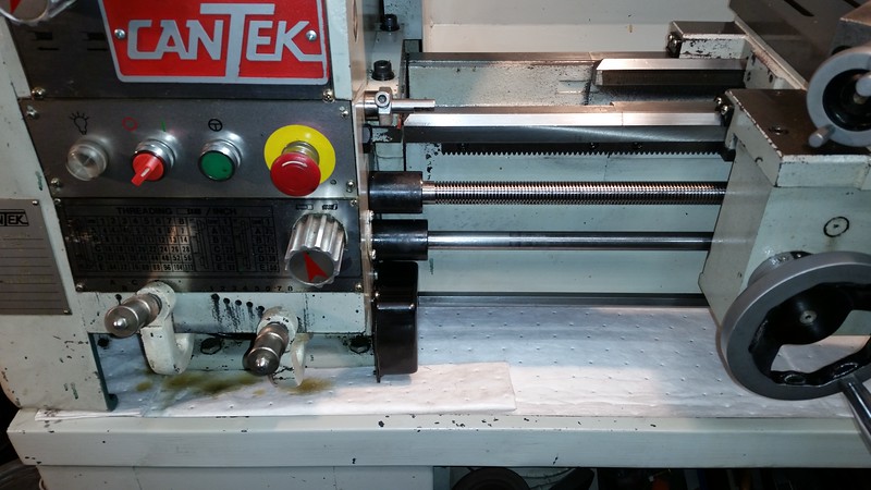
My question is, why does his lathe stop on a dime like that? I don't have a brake, mechanical or electrical. But when I power off I have to allow for wind down deceleration. Do some machines have inductive off or something? His switch & knob looks different.


kylemp

Well-Known Member
I'd agree he's running a vfd.. which you can get almost instant stops if it's set up right. You can also put an electromagnetic brake on yours and have it wired to disengage when you turn the spindle on if you want to mimick what he's able to do. Or put a vfd and 3 phase motor on.
 

PeterT

Ultra Member
Premium Member
I'm at the infancy noob evaluation stage of VFD. I can certainly see the advantages though. Links below show some added proximity stop enhancements.

What I cant quite get my head around is how standalone is a VFD lathe conversion. I just assumed (hoped?) you replaced the the existing motor with VFD motor, programmed the VFD control box & away you go. Leaving the internal electric boards & fuses bypassed & unscathed. But looks like some VFD systems tie into the existing electrics, maybe to utilize the carriage FWD/REV lever? I don't have flood coolant pump, so that simplifies things. Its basically on/off fwd/rev & mechanical speed selection. The carriage lever is certainly handy & almost hard-wired to my brain now, but I guess if I had to flick a different switch that wouldn't be the end of the world. I was toying with the idea of getting a 110v VFD & replacing my drill press motor just as a lower cost learning exercise. It would give me more rpm control & save me messing with belts which I by & large ignore out of laziness.

https://www.hobby-machinist.com/threads/pm1340gt-lathe-threading-with-a-proximity-stop.45977/
https://www.hobby-machinist.com/threads/vfd-proximity-sensor-stop.32816/
https://www.hobby-machinist.com/thr...trol-system-with-proximity-stop-update.63426/
 

PeterT

Ultra Member
Premium Member

Dabbler

ersatz engineer
The sky's the limit! the easiest conversion is as you say, motor and VFD. David turned the lathe into a custom Porsche! Wow! Thanks for the link...
 
Last edited:

PeterT

Ultra Member
Premium Member
This video series shows some of the details involved with VFD conversion - replacing the old motor & everything thereafter is add-on. Looks like a nice end result on a noble refurbished Southbend.


Johnwa

Ultra Member
I like where he has the controls in the first video. The controls on my lathe are on the front of the stand just above knee level!?? I haven’t hooked them into the vfd yet but now I know I will move them to a more useful location.
 

Johnwa

Ultra Member
I’m a noob. It’s a 2.2 kW vfd with a 1.5hp motor. It’s pretty simple to get up and running. Adding the remote controls looks simple enough but is a bit more complicated. The braking looks interesting.
 

PeterT

Ultra Member
Premium Member
My friend was telling me about weird 'interference' type issues with VFD's plugged in & running, like other appliances, scratchy sound on a boom box, clocks turning backwards... LOL. Do you experience any of that? In the 2nd Southbend vid about 17:00 he wraps some wires with copper tape. Is that intending to shield the VFD side or the shop side do you think?

In the 3rd video where he talks about programming features, it looks like that particular controller has provisions to act on a signal (like carriage stop). Would you say this is pretty common to these boxes or you would have to ensure it had that capability beforehand?
 

Johnwa

Ultra Member
I can’t comment any interference issues. I’m sure there is some but if the vfd meets CE requirements it should be ok.

Including grounds, mine has about 20 control terminals. In my limited experience there are only two of significance, forward and reverse. Connecting either terminal to ground starts the motor. You can use different relays, limit switches etc to control those terminals. For example you could have a limit switch that the carriage bumps up against to break the control signal.

Using shielded control cables is a good idea even without a vfd. The control signals are low voltage and amperage. The noisy, high amps driving the motor can induce noise in the control wires and cause false signals to occur.
 

Dabbler

ersatz engineer
Most VFD manuals suggest to use short leads on the 3PH side, to reduce inductance and interference. Sounds like shielding them couldn't hurt!
 

JohnW

(John)
In my recent lathe rebuild, I incorporated a VFD to control the 5hp 3ph motor. I gutted the lathe wiring and completely re-designed the electrics to properly (in my little mind at least) integrate it into the lathe and take advantage of the capabilities of the VFD.

The simple route is to power just the motor from the VFD, and then use the VFD controls (some VFD's don't have front panel controls) to control the motor speed and direction.

The more integrated route replaces all of the existing lathe wiring so that the carriage mounted F/R lever, on/off switches/button, jog button(s), brake switches and the like are integrated.

On the other hand, I like playing with wiring so completely re-designing the wiring just added to the "pleasure" of the lathe rebuild.
 

PeterT

Ultra Member
Premium Member
Thanks John. I forgot about jog. That's another thing I don't have on my lathe but would have to be integrated into conversion. So using that as example, do you somehow wire that existing button into a specific VFD terminal & program what it does?
 

JohnW

(John)
Most VFD's have big manuals (100+ pages) that describe all the things they can do, but for the most part they are pretty simple.

There are some analog and digital inputs that can do various things. All of the inputs are low-voltage (typically 10VDC), and very low current so relatively thin wires (i.e. 20-26 AWG is enough) can be used. There are no electrical safety issues with the wires, although you do want to be careful so a loose or damaged wire cannot suddenly turn the lathe on.

What the inputs do is set by the programming of options in the VFD. The digital inputs can signal such things as FWD, REV, JOG, Motor Enable, Brake, etc.

The analog inputs can do things like control the motor speed remotely. The most common use of that is to place a potentiometer on the front of the lathe that controls the frequency sent to the motor. You can program the maximum and minimum frequencies to be sent to the motor. It is common to set the minimum to something like 5Hz, so you can run it very slowly (it will still have almost full torque at that speed), 60Hz for normal operation, and up to as much as 120Hz (often as high as 200Hz is available) to run everything at double speed.

You need to be careful as the motor can over heat at very low speeds since it will produce almost as much heat at slow speeds, but any built-in cooling fan will be blowing almost no air. I solved that by using the relay output that is available on the VFD. I programmed it to turn on whenever power is being applied to the motor. The relay then runs a powerful 24V fan that is directed at the motor.

You need to be careful that the VFD's output frequency / voltage curve is set properly to reduce the voltage applied to the motors as the frequency is decreased as well. The default setting is usually pretty close to what is required.

Running the motor at a frequency higher than its nameplate rating can damage bearings, or in extreme cases make the armature fly apart. Generally 90Hz (150% speed) is not an issue. At any frequency beyond the nameplate rating the motor will start to have less and less torque though.

My VFD is an Alan-Bradley (aka AB). You can program one of the inputs to be JOG. At the same time you can specify what the output frequency should be in JOG mode. It is nice to JOG at low speed, so I think I specified 6Hz. That means it will jog at 1/10 the usual 60Hz speed.

After that it gets a bit more complicated since you may also be able to set a different acceleration profile for the JOG input.

I have my lathe set for about a 3 second acceleration period, so when I press JOG, it takes 3 seconds to go from 0Hz to 6 Hz. That means a half second press will only accelerate to a couple of Hz, and only slowly move the chuck a fraction of a turn. The same accel/decel curve is used when going into forward or reverse mode. You can switch it from full forward to full reverse, and it takes 3 seconds to decel to a stop, and then another 3 seconds to accel to full reverse with no excess loads on anything.

When I apply the foot brake lightly, it applies a normal decal curve (3 secs), but if I press it harder it applies a 0.1 second decel curve so it will very quickly come to a stop (especial

Ideally you would want a relatively fast decelleratio0n curve on JOGging, since you are not turning it very fast, and probably want it to stop quickly.

Some day soon, I will update my lathe rebuild thread with an electrical posting an show what I have done. I haven't updated that thread in over a year.
 

John Conroy

member
Premium Member
Peter, I think your lathe does have a "jog" button. It's the green one beside the E-stop. I use mine occasionally.

 
Top